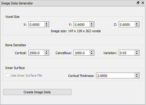
Orient3D: Image Data Generator

This widget creates 3D image data from surface models of objects. X4D tracks objects in X-ray images by generating DRRs from 3D image data (usually CT) of the objects. In some cases CT data is not appropriate for a particular subject and only surface models are available. These surface models could be CAD files of metal implants, or surfaces made from MRI or some other imaging modality that does not represent bone density. This widget creates simulated CT data from the surface models so that the objects can be tracked in X4D. For implants you would typically start with a CAD model of the device, and create a solid object within the image data. For bones, it is recommended that you obtain an outer surface (the outer boundary of the cortical bone), and an inner surface (the inner boundary of the cortical bone), to create more realistic image data. If an inner surface is not available, you can specify the cortical thickness in order to create a shell of constant depth.
Note: this widget is only available when the computer has a CUDA-capable graphics card installed.
| Voxel Size |
|---|
|
These fields specify the XYZ dimensions of the voxels in model units (usually mm). As you change the values, the voxel count of the resulting image is updated. |
| Bone Densities |
|---|
|
Cortical The density of the voxels at the outer boundary of the cortical bone. Cancellous The density of the voxels in the center of the bone. If an inner surface is defined, these are the voxels inside the inner surface. If no inner surface is defined, these are the voxels in the object that are more than cortical thickness from the outer surface. Variation The percent variation (noise) in densities in the cortical and cancellous regions of bone. Adding noise can make the image data look more realistic, and it helps reduce undesirable edge artifacts when performing edge detection on DRRs made from the image data. Note: The voxels between the inner and outer surfaces are not all given the cortical density (+/- the variation), because this produces a double edge in the edge detected DRR that is not in the X-ray images. Instead the voxels are given the cortical density right at the outer boundary, and then ramp down to the cancellous density at the inner boundary. This produces a DRR edge image that better matches the X-ray edge image. |
| Inner Surface |
|---|
|
If the current object has an OBJ file defining the inner surface of the cortical bone, the Use Inner Surface checkbox will be enabled. If the box is checked, this inner surface will be used when creating the image data. Voxels between the inner and outer surfaces will be given the specified cortical density, and voxels inside the inner surface will be given the specified cancellous density. If the box is not checked, the Cortical Thickness field is enabled. A cortical thickness of -1 means there is no inner boundary, so all voxels inside the outer surface will be given the cortical density. A value greater than zero will create an inner surface that is a constant distance (the specified thickness) from the outer surface. Voxels between the surfaces will have cortical density, and voxels inside the inner surface will have cancellous density. |
| Create Image Data |
|---|
|
Pressing this button creates the image data. The resulting TIFF file will be added to object definition in the subject file, replacing any previously defined image file. |