Segment Inertia
| Language: | English • français • italiano • português • español |
|---|
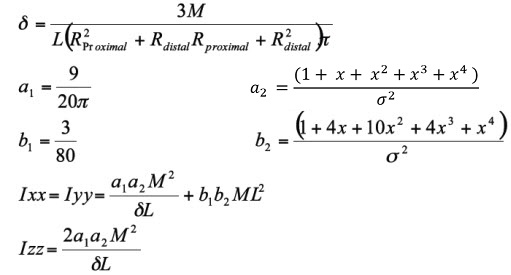
By default the moment of inertia of a segment is computed from the segment mass, the proximal and distal radii, and the Segment Geometry.
The default Visual3D segments are treated as geometric objects that have inertial properties based on their shape.
Hanavan E. (1964) A Mathematical Model for the Human Body. Technical Report, Wright-Patterson Air Force Base.
Please refer to Transforming Segment Moment of Inertia for details on transforming moment of inertia from one Coordinate System into another Coordinate System.
Inertial properties of a Cone (Conical Frustrum)
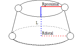
One of the Visual3D segment geometries is labeled a Cone. To be precise the Cone refers to a conical frustrum. A frustra of right cones is created by cutting the top off of a cone such that the cut is parallel to the base of the cone.
A frustra of right cones is created by cutting the top off of a cone such that the cut is parallel to the base of the cone.
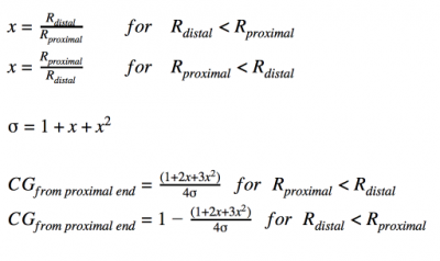
For a unit length, the center of mass relative to the proximal end of the segment is located at:
given: M= segment mass, and L= segment length
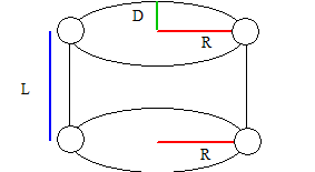
Inertial properties of an Elliptical Cylinder
The distance from the proximal end of the segment to the center of mass of the segment.
CG_from_proximal_end = 0.5*L
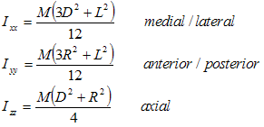
The moment of inertia of a cylinder. (assuming the default Visual3D coordinate system)
Visual3D uses the Radius at the distal end of the segment as the Radius of the cylinder.
Inertial Properties of a Sphere
Defining a Spherical Segment
For segments modeled as spheres, Visual3D requires a proximal segment radius and a distal segment radius. The inertial properties of the segment are calculated using only the distal radius. However, the proximal radius is still required to determine the location of the proximal segment end. If both a medial and a lateral target are used at one end of a segment during subject calibration, then the radius at that end is determined to be one-half of the distance between these targets. If only a single target is used at the end of a segment then a qualifier, either DIST_RAD or PROX_RAD, must be used. One notable difference arises in creating spherical segments. Visual3D expects the distal targets to be located at 50% of the distance between segment ends. This allows the distal radius to produce a realistic measure of the dimension of the sphere.
The distance from the proximal end of the segment to the center of mass of the segment.
CG_from_proximal_end = L
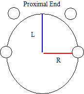
The moment of inertia of an sphere. (assuming the default Visual3D coordinate system)
Visual3D uses the Radius at the distal end of the segment as the Radius of the Sphere. The Length of the Sphereis from the Proximal End to the Distal End of the segment.
Inertial Properties of an Ellipsoid
The distance from the proximal end of the segment to the center of mass of the segment.
CG_from_proximal_end = L
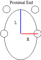
The moment of inertia of an ellipsoid. (assuming the default Visual3D coordinate system)
Visual3D uses the Radius at the distal end of the segment as the Radius of the Ellipsoid. The Length of the Ellipsoid is from the Proximal End to the Distal End of the segment.
Entering Inertial Values Using Expressions
It is possible to include any regression equations for the inertia and center of mass because Visual3D allows the user to put expressions into the edit boxes. Refer to Entering Inertial Values Using Expressions for more details.
Adjusted Zatsiorsky-Seluyanov's segment inertia parameters
Using the Adjusted Zatsiorsky-Seluyanov's segment inertia parameters in Visual3D instead of the default Dempter's and Hanavan's.
