Tutorial: Bicycle Pedal and Crank
| Language: | English • français • italiano • português • español |
|---|
Given a c3d file with one marker on each pedal of a stationary bicycle, create crank and pedal segments.
The tutorial files can be found here
Open the Movement Trial
- Open the file Pedal_Motion.c3d
- Note that there are only two markers.
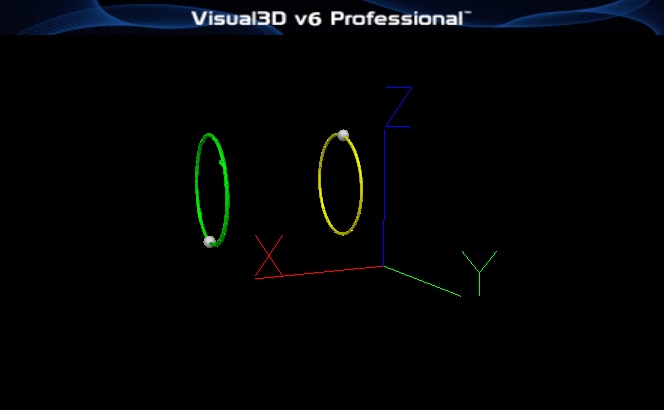
- Highlight the path of the markers as trails.
- Select the TARGET u1 with a right mouse click.
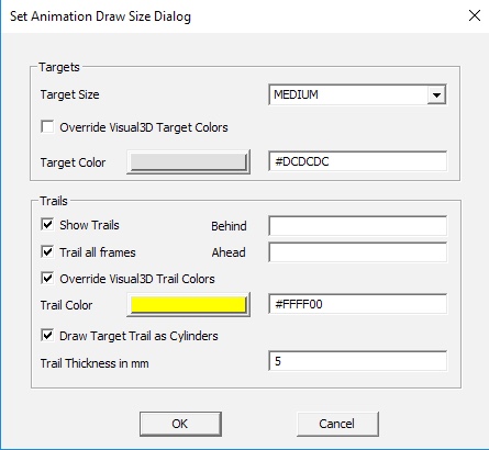
- Select the option "Draw Target Properties"
- Select the options to draw the trail and specify the color.
- The circular path of each marker should be drawn in the animation.
Create the Model
Apply the Model Template
- Apply the model template pedal.mdh that was part of the zip file downloaded
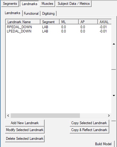
- Note that there are only two landmarks
- Note that there are 6 segments, but none of them has been built because of missing information.
- There should be many error messages at this point.
- We will add in the missing information using pipeline commands.
Create virtual targets and landmarks
Created virtual targets and landmarks based on the circular path of the markers on the pedals.
The underlying assumptions are that the crank rotates about a fixed axis, the pedals sit at the end of the crank and rotate with the crank axis, but are always oriented vertically.
First, make the movement trial the active file
Second, create TARGETS for the center of the path of each marker and for a marker 0.1 meters along the normal to that path.
- Create_Target
- /SIGNAL_NAMES=RCENTER+RNORMAL+LCENTER+LNORMAL
- ! /SIGNAL_DESCRIPTION=
- /EXPRESSION='Best_Fit_Circle(TARGET::ORIGINAL::U1)','Vector(TARGET::ORIGINAL::RCENTER,0)-0.1*Best_Fit_Plane(TARGET::ORIGINAL::U1)','Best_Fit_Circle(TARGET::ORIGINAL::U2)','Vector(TARGET::ORIGINAL::LCENTER,0)-0.1*Best_Fit_Plane(TARGET::ORIGINAL::U2)'
- ! /INCLUDE_MOTIONFILE=TRUE
- ! /INCLUDE_CALFILE=FALSE
- ;
This command uses the Evaluate_Expression function Best_Fit_Circle(TARGET::ORIGINAL::U2) to find the center and radius of a circle that best fits the path of the marker.
Third, based on the location of these targets in the movement trial, create associated landmarks.
- Add_Landmark
- /LANDMARK_NAME=RCENTER
- ! /CALIBRATION_FILE=
- ! /USER_GENERATED=TRUE
- ! /USE_PERCENTAGE=FALSE
- ! /CALIBRATION_ONLY=FALSE
- ! /USE_TARGETS=FALSE
- /SEGMENT_NAME=LAB
- ! /TARGET_TYPES=
- ! /TARGET_NAMES=
- /MCS_ML=@Eval(Mean(TARGET::ORIGINAL::RCENTER)[1,1])
- /MCS_AP=@Eval(Mean(TARGET::ORIGINAL::RCENTER)[1,2])
- /MCS_AXIAL=@Eval(Mean(TARGET::ORIGINAL::RCENTER)[1,3])
- ! /LANDMARK_LOCATION=
- ! /REFERENCE_LOCATION_TYPE=
- ! /REFERENCE_LOCATION_NAME=
- ! /USE_REFERENCE_LOCATION=FALSE
- ;
This command takes advantage of the @Eval() function in the pipeline parameters. The command evaluates the expression based on the data in the active movement file, then assigns the values to the Add_Landmark command.
- Add_Landmark
- /LANDMARK_NAME=RNORMAL
- ! /CALIBRATION_FILE=
- ! /USER_GENERATED=TRUE
- ! /USE_PERCENTAGE=FALSE
- ! /CALIBRATION_ONLY=FALSE
- ! /USE_TARGETS=FALSE
- /SEGMENT_NAME=LAB
- ! /TARGET_TYPES=
- ! /TARGET_NAMES=
- /MCS_ML=@Eval(Mean(TARGET::ORIGINAL::RNORMAL)[1,1])
- /MCS_AP=@Eval(Mean(TARGET::ORIGINAL::RNORMAL)[1,2])
- /MCS_AXIAL=@Eval(Mean(TARGET::ORIGINAL::RNORMAL)[1,3])
- ! /LANDMARK_LOCATION=
- ! /REFERENCE_LOCATION_TYPE=
- ! /REFERENCE_LOCATION_NAME=
- ! /USE_REFERENCE_LOCATION=FALSE
- ;
- Add_Landmark
- /LANDMARK_NAME=RCENTER_UP
- ! /CALIBRATION_FILE=
- ! /USER_GENERATED=TRUE
- ! /USE_PERCENTAGE=FALSE
- ! /CALIBRATION_ONLY=FALSE
- ! /USE_TARGETS=FALSE
- /SEGMENT_NAME=LAB
- ! /TARGET_TYPES=
- ! /TARGET_NAMES=
- /MCS_ML=@Eval(Mean(TARGET::ORIGINAL::RCENTER)[1,1])
- /MCS_AP=@Eval(Mean(TARGET::ORIGINAL::RCENTER)[1,2])
- /MCS_AXIAL=@Eval(Mean(TARGET::ORIGINAL::RCENTER)[1,3]+0.001)
- ! /LANDMARK_LOCATION=
- ! /REFERENCE_LOCATION_TYPE=
- ! /REFERENCE_LOCATION_NAME=
- ! /USE_REFERENCE_LOCATION=FALSE
- ;
- Add_Landmark
- /LANDMARK_NAME=LCENTER
- ! /CALIBRATION_FILE=
- ! /USER_GENERATED=TRUE
- ! /USE_PERCENTAGE=FALSE
- ! /CALIBRATION_ONLY=FALSE
- ! /USE_TARGETS=FALSE
- /SEGMENT_NAME=LAB
- ! /TARGET_TYPES=
- ! /TARGET_NAMES=
- /MCS_ML=@Eval(Mean(TARGET::ORIGINAL::LCENTER)[1,1])
- /MCS_AP=@Eval(Mean(TARGET::ORIGINAL::LCENTER)[1,2])
- /MCS_AXIAL=@Eval(Mean(TARGET::ORIGINAL::LCENTER)[1,3])
- ! /LANDMARK_LOCATION=
- ! /REFERENCE_LOCATION_TYPE=
- ! /REFERENCE_LOCATION_NAME=
- ! /USE_REFERENCE_LOCATION=FALSE
- ;
- Add_Landmark
- /LANDMARK_NAME=LNORMAL
- ! /CALIBRATION_FILE=
- ! /USER_GENERATED=TRUE
- ! /USE_PERCENTAGE=FALSE
- ! /CALIBRATION_ONLY=FALSE
- ! /USE_TARGETS=FALSE
- /SEGMENT_NAME=LAB
- ! /TARGET_TYPES=
- ! /TARGET_NAMES=
- /MCS_ML=@Eval(Mean(TARGET::ORIGINAL::LNORMAL)[1,1])
- /MCS_AP=@Eval(Mean(TARGET::ORIGINAL::LNORMAL)[1,2])
- /MCS_AXIAL=@Eval(Mean(TARGET::ORIGINAL::LNORMAL)[1,3])
- ! /LANDMARK_LOCATION=
- ! /REFERENCE_LOCATION_TYPE=
- ! /REFERENCE_LOCATION_NAME=
- ! /USE_REFERENCE_LOCATION=FALSE
- ;
- Add_Landmark
- /LANDMARK_NAME=LCENTER_UP
- ! /CALIBRATION_FILE=
- ! /USER_GENERATED=TRUE
- ! /USE_PERCENTAGE=FALSE
- ! /CALIBRATION_ONLY=FALSE
- ! /USE_TARGETS=FALSE
- /SEGMENT_NAME=LAB
- ! /TARGET_TYPES=
- ! /TARGET_NAMES=
- /MCS_ML=@Eval(Mean(TARGET::ORIGINAL::LCENTER)[1,1])
- /MCS_AP=@Eval(Mean(TARGET::ORIGINAL::LCENTER)[1,2])
- /MCS_AXIAL=@Eval(Mean(TARGET::ORIGINAL::LCENTER)[1,3]+0.001)
- ! /LANDMARK_LOCATION=
- ! /REFERENCE_LOCATION_TYPE=
- ! /REFERENCE_LOCATION_NAME=
- ! /USE_REFERENCE_LOCATION=FALSE
- ;
Lastly Build the Model
- Build_Model
- ! /CALIBRATION_FILE=
- ! /REBUILD_ALL_MODELS=FALSE
- ! /DISPLAY_RESULTS=TRUE
- ;
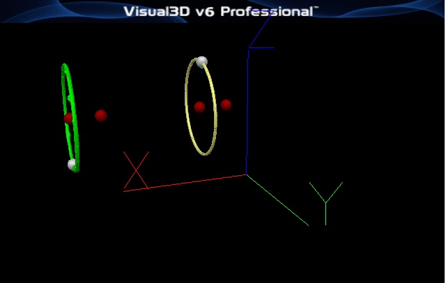
The resulting model and movement trial are:
Modeling Details
- Two IK chains were constructed, one for each pedal.
- Note that the root segment of the chain has all translations and rotations constrained. The problem is that we don't want the pedal constrained to the LAB, but to the location of the marker on the pedal.
- We specified this using Motion Constraints. Selected the Properties Tab
 The origin of the reference for the crank is placed just above the center of the marker path and rotated 180 degrees about the vertical axis of the lab.
The crank and pedal are then given one degree of freedom about the X-axis, and one tracking marker.


