Tutorial: Gait Events
| Language: | English • français • italiano • português • español |
|---|
(( Under Development.....))
Gait Events, such as Heel Strike and Toe Off, are commonly used to identify gait cycles, and normalize signals accordingly. Generally, using force platforms is the most accurate method to automatically identify gait events. However, when force platforms are not available, or due to certain gait pathologies, it is also possible to identify gait events manually. This tutorial describes the different ways to create gait events.
Gait Event Acronyms
Definitions of the gait event acronyms used in Visual3D
The automatic gait events command and many of the events created in the tutorials, and used in the example files have 3 (or 4) character labels that have been used consistently albeit cryptically. These acronyms are historical and derive from the early versions of software that read C3D files because the original C3D format allowed a maximum of characters for an Event Label.
These Event labels are divided into two categories. The kinematically based categories include:
- RHS= Right Heel Strike
- RTO= Right Toe Off
- LHS= Left Heel Strike
- LTO= Left Toe Off
The kinetically based categories refer to those events that describe contact with a force platforms.
- RON= Right On
- ROFF= Right Off
- LON= Left On
- LOFF= Left Off
All RON events are also RHS events, but RON events are only created when contact is made with a force platform. This provides a means to declare a range of data for reporting only when in contact with the force platform because Joint Moments and Joint Powers for example to not have meaningful data when the foot is in contact with ground but no ground reaction forces are measured.
Using the Ground Reaction Force
If Force Platform data exists, and if Visual3D model segments have been created, Visual3D can detect contact with the force platform and compute the appropriate event labels.
- Open the Command Pipeline
- Expand the Event Creation folder
- Double click with the Left Mouse Button on the Automatic_Gait_Events command
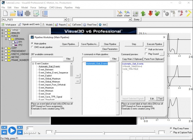
- Double click with the Left Mouse Button on the Automatic_Gait_Events command in the processing list box.
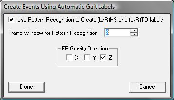
- Select the direction of gravity. For this file select Z
- Execute the Pipeline
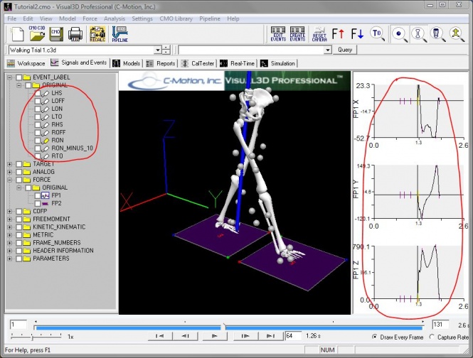
- Several Events have been created and highlighted on the graphs.


Creating Events Manually
- Select the graph of the Z-component of the Ground Reaction Force signal by Left clicking on the graph. You will see the graph is now framed.
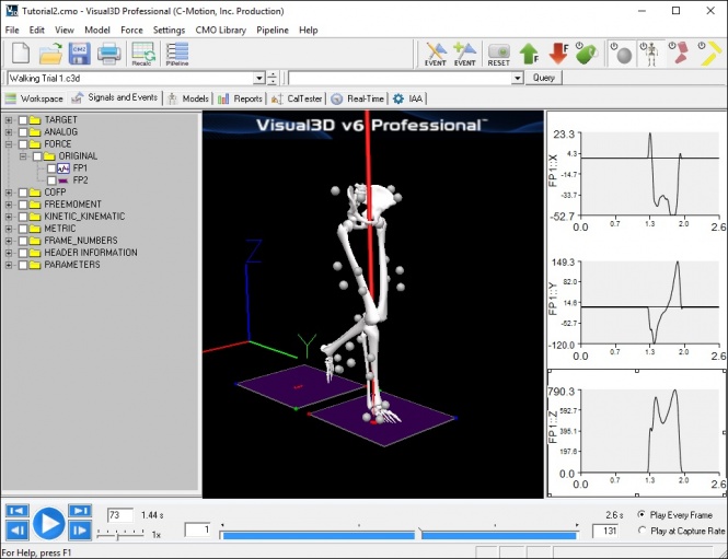
- To create the event, double click on the Fz force signal at the frame that the signal rises above zero.
- Enter the name RON into the popup dialog box. RON is a typical name used in Visual3D to indicate that the Right has contacted a force platform. In principle the event can be assigned any name, but when Visual3D computes Heel Strike and Toe Off automatically, the events are labeled ON and OFF.
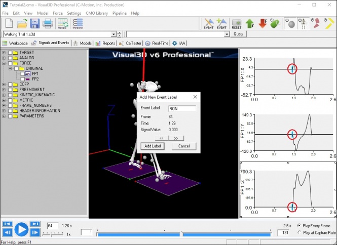
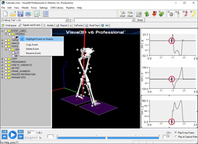
- An event labeled RON has been added to the Event_Label data tree.
- To highlight this event (actually all occurrences of this event), select the RON signal with a Right Mouse Button click and select Highlight Event on Graphs. The Frames corresponding to RON will be highlighted in yellow on all signals in each graph.


Create Events Dialog


Using TPR to identify other instances
TPR signal is based on matching data from a range of frames against the same (or a different signal). When the two ranges match an Event Label is created at the midpoint of the range. For example, if one occurrence of heel strike has been identified, this command can be used to determine all other heel strike events in a file.
| Event_TPR_Signal | |
| /Pattern_File= | The file from which to find the pattern signal. If this is blank, the pattern signal is taken from each trial. |
| /Pattern_Type= | The type of signal used as the test signal. |
| /Pattern_Name= | The names of the signals used as the test signal. |
| /Pattern_Folder= | The name of the signal folder used as the test signal. |
| /Signal_Types= | The type of signal to be compared with the test signal. |
| /Signal_Names= | The names of the signals to be compared with the test signal. |
| /Signal_Folder= | The name of the signal folder compared with the test signal. |
| /Pattern_Event_Name= | The event at which the pattern signal is centered. |
| /Pattern_Event_Instance= | The occurence of the event at which the pattern signal is centered. |
| /Event_Name= | The name to be given to the threshold event. |
| /Select_X= | (True or False)Use this component of the signals. |
| /Select_Y= | (True or False)Use this component of the signals. |
| /Select_Z= | (True or False)Use this component of the signals. |
| /TPR_Radius= | The range of frames of data used for the comparison. |
| /Tolerance= | The "goodness of fit" for the match. |

Dialog that pops up when pipeline selection is edited by double clicking with the left mouse button.
The graph to the right of the dialog displays the pattern signal that will be used. Changing the radius will change the number of frames used.
The Pattern file specifies the file that is to be used for the test signal. If Rotate Through Files is selected then the test signal is created from each file and used for the TPR of that file. If the File is specified then the test signal is defined from one file and used for all other files. A description of the use of TPR for determining gait events when a force platform signal is present is presented in the following article.
Stanhope SJ, Kepple TM, McGuire DA, Roman NL.(1990) "A Kinematic-Based Technique for Event Time Determination During Gait." Medical and Biological Engineering and Computing 28:355-360.
Kinematic Only Identification
Computing gait events from only kinematic data is challenging, especially for subjects with movement disorders. The following example is based on the following article published in 2008.
We have made some modest changes to the algorithm to make it more general for Visual3D users. This page shows 2 methods for computing gait events without GRF.
Another option to consider is:
Transform Heel and Toe markers into Pelvis Coordinate System
First, transform the right and left heel and toe markers into the pelvis segment coordinate system. (this removes the need to specify the direction that the subject is walking). This can be accomplished using the model based item TARGET_PATH. The images below show the settings used.


Method 1. Coordinate Based Algorithm
This method uses the maximum and minimum anterior component of RHEEL_WRT_PELVIS, LHEEL_WRT_PELVIS, RTOE_WRT_PELVIS, and LTOE_WRT_PELVIS to find the foot strikes and toeoffs. For the default Visual3D pelvis, the anterior direction is in the y-direction.
Right Heel Strike
Heel Strike is defined as the maximum values of the signal.
Maximum
/SIGNAL_TYPES=LINK_MODEL_BASED
/SIGNAL_NAMES=RHEEL_WRT_PELVIS
! /SIGNAL_FOLDER=ORIGINAL
/EVENT_NAME=RHS
! /SELECT_X=FALSE
/SELECT_Y=TRUE
! /SELECT_Z=FALSE
! /FRAME_WINDOW=8
! /START_AT_EVENT=
! /END_AT_EVENT=
/EVENT_INSTANCE=0
;

the yellow tick represents RON from the force platform signal.
the red tick represents RHS from the command
Left Heel Strike
Maximum
/SIGNAL_TYPES=LINK_MODEL_BASED
/SIGNAL_NAMES=LHEEL_WRT_PELVIS
! /SIGNAL_FOLDER=ORIGINAL
/EVENT_NAME=LHS
! /SELECT_X=FALSE
/SELECT_Y=TRUE
! /SELECT_Z=FALSE
! /FRAME_WINDOW=8
! /START_AT_EVENT=
! /END_AT_EVENT=
/EVENT_INSTANCE=0
;

the yellow tick represents ROFF from the force platform signal.
the red tick represents RTO from the command
Right Toe Off
Toe off is defined as the minimum values of the signal.
Minimum
/SIGNAL_TYPES=LINK_MODEL_BASED
/SIGNAL_NAMES=RTOE_WRT_PELVIS
! /SIGNAL_FOLDER=ORIGINAL
/EVENT_NAME=RTO
! /SELECT_X=FALSE
/SELECT_Y=TRUE
! /SELECT_Z=FALSE
! /FRAME_WINDOW=8
! /START_AT_EVENT=
! /END_AT_EVENT=
/EVENT_INSTANCE=0
;

the yellow tick represents ROFF from the force platform signal.
the red tick represents RTO from the command
Left Toe Off
Minimum
/SIGNAL_TYPES=LINK_MODEL_BASED
/SIGNAL_NAMES=LTOE_WRT_PELVIS
! /SIGNAL_FOLDER=ORIGINAL
/EVENT_NAME=LTO
! /SELECT_X=FALSE
/SELECT_Y=TRUE
! /SELECT_Z=FALSE
! /FRAME_WINDOW=8
! /START_AT_EVENT=
! /END_AT_EVENT=
/EVENT_INSTANCE=0
';

the yellow tick represents LOFF from the force platform signal.
the red tick represents LTO from the command
Method 2. Velocity Based Algorithm
The velocity based algorithm is essentially t=he same. The zero crossing of the first derivative to the model based items computed above (LHEEL_WRT_PELVIS, RHEEL_WRT_PELVIS, RTOE_WRT_PELVIS, and LTOE_WRT_PELVIS) are computed.
! Compute the velocity signals

First_Derivative
/SIGNAL_TYPES=LINK_MODEL_BASED+LINK_MODEL_BASED+LINK_MODEL_BASED+LINK_MODEL_BASED
/SIGNAL_NAMES=LHEEL_WRT_PELVIS+LTOE_WRT_PELVIS+RHEEL_WRT_PELVIS+RTOE_WRT_PELVIS
/SIGNAL_FOLDER=ORIGINAL+ORIGINAL+ORIGINAL+ORIGINAL
! /RESULT_SUFFIX=
/RESULT_FOLDER=VELOCITY
;

! compute events based on threshold crossings
Right Heel Strike
This command finds the desending zero crossing of the velocity of the heel wrt to pelvis to find the heel strike.
Threshold
/SIGNAL_TYPES=LINK_MODEL_BASED
/SIGNAL_NAMES=RHEEL_WRT_PELVIS
/SIGNAL_FOLDER=VELOCITY
/EVENT_NAME=RHS
! /SELECT_X=FALSE
/SELECT_Y=TRUE
! /SELECT_Z=FALSE
! /SELECT_RESIDUAL=FALSE
/THRESHOLD=0
! /FRAME_WINDOW=8
! /FRAME_OFFSET=0
! /ASCENDING=FALSE
/DESCENDING=TRUE
/ENSURE_RANGE_FRAMES_BEFORE_THRESHOLD_CROSSING=TRUE
/ENSURE_RANGE_FRAMES_AFTER_THRESHOLD_CROSSING=TRUE
! /START_AT_EVENT=
! /END_AT_EVENT=
/EVENT_INSTANCE=0
;

Right Toe Off
This command finds the ascending zero crossing of the velocity of the toe wrt to pelvis to find the toe off.
Threshold
/SIGNAL_TYPES=LINK_MODEL_BASED
/SIGNAL_NAMES=RTOE_WRT_PELVIS
/SIGNAL_FOLDER=VELOCITY
/EVENT_NAME=RTO
! /SELECT_X=FALSE
/SELECT_Y=TRUE
! /SELECT_Z=FALSE
! /SELECT_RESIDUAL=FALSE
/THRESHOLD=0
! /FRAME_WINDOW=8
! /FRAME_OFFSET=0
/ASCENDING=TRUE
/DESCENDING=FALSE
/ENSURE_RANGE_FRAMES_BEFORE_THRESHOLD_CROSSING=TRUE
/ENSURE_RANGE_FRAMES_AFTER_THRESHOLD_CROSSING=TRUE
! /START_AT_EVENT=
! /END_AT_EVENT=
/EVENT_INSTANCE=0
;

Left Heel Strike
Threshold
/SIGNAL_TYPES=LINK_MODEL_BASED
/SIGNAL_NAMES=LHEEL_WRT_PELVIS
/SIGNAL_FOLDER=VELOCITY
/EVENT_NAME=LHS
! /SELECT_X=FALSE
/SELECT_Y=TRUE
! /SELECT_Z=FALSE
! /SELECT_RESIDUAL=FALSE
/THRESHOLD=0
! /FRAME_WINDOW=8
! /FRAME_OFFSET=0
! /ASCENDING=FALSE
/DESCENDING=TRUE
/ENSURE_RANGE_FRAMES_BEFORE_THRESHOLD_CROSSING=TRUE
/ENSURE_RANGE_FRAMES_AFTER_THRESHOLD_CROSSING=TRUE
! /START_AT_EVENT=
! /END_AT_EVENT=
/EVENT_INSTANCE=0
;

Left Toe Off
Threshold
/SIGNAL_TYPES=LINK_MODEL_BASED
/SIGNAL_NAMES=LTOE_WRT_PELVIS
/SIGNAL_FOLDER=VELOCITY
/EVENT_NAME=LTO
! /SELECT_X=FALSE
/SELECT_Y=TRUE
! /SELECT_Z=FALSE
! /SELECT_RESIDUAL=FALSE
/THRESHOLD=0
! /FRAME_WINDOW=8
! /FRAME_OFFSET=0
/ASCENDING=TRUE
/DESCENDING=FALSE
/ENSURE_RANGE_FRAMES_BEFORE_THRESHOLD_CROSSING=TRUE
/ENSURE_RANGE_FRAMES_AFTER_THRESHOLD_CROSSING=TRUE
! /START_AT_EVENT=
! /END_AT_EVENT=
/EVENT_INSTANCE=0
;

As can be observed the results for Control data are very good.
NOTE: That the results for patients diagnosed with Movement Disorders are not nearly so good.
Pipeline Script for Calling Compute_Gait_Events_Without_GRF Meta Command
Example Pipeline command for calling the Compute_Gait_Events_Without_GRF Meta Command
Compute_Model_Based_Data
/RESULT_NAME=RHEEL_WRT_PELVIS
/FUNCTION=TARGET_PATH
/SEGMENT=RHEEL
/REFERENCE_SEGMENT=RPV
/RESOLUTION_COORDINATE_SYSTEM=RPV
! /USE_CARDAN_SEQUENCE=FALSE
! /NORMALIZATION=FALSE
! /NORMALIZATION_METHOD=
! /NORMALIZATION_METRIC=
! /NEGATEX=FALSE
! /NEGATEY=FALSE
! /NEGATEZ=FALSE
! /AXIS1=X
! /AXIS2=Y
! /AXIS3=Z
;

Compute_Model_Based_Data
/RESULT_NAME=LHEEL_WRT_PELVIS
/FUNCTION=TARGET_PATH
/SEGMENT=LHEEL
/REFERENCE_SEGMENT=RPV
/RESOLUTION_COORDINATE_SYSTEM=RPV
! /USE_CARDAN_SEQUENCE=FALSE
! /NORMALIZATION=FALSE
! /NORMALIZATION_METHOD=
! /NORMALIZATION_METRIC=
! /NEGATEX=FALSE
! /NEGATEY=FALSE
! /NEGATEZ=FALSE
! /AXIS1=X
! /AXIS2=Y
! /AXIS3=Z
;

Compute_Model_Based_Data
/RESULT_NAME=RTOEL_WRT_PELVIS
/FUNCTION=TARGET_PATH
/SEGMENT=RTOE
/REFERENCE_SEGMENT=RPV
/RESOLUTION_COORDINATE_SYSTEM=RPV
! /USE_CARDAN_SEQUENCE=FALSE
! /NORMALIZATION=FALSE
! /NORMALIZATION_METHOD=
! /NORMALIZATION_METRIC=
! /NEGATEX=FALSE
! /NEGATEY=FALSE
! /NEGATEZ=FALSE
! /AXIS1=X
! /AXIS2=Y
! /AXIS3=Z
;

Compute_Model_Based_Data
/RESULT_NAME=LTOE_WRT_PELVIS
/FUNCTION=TARGET_PATH
/SEGMENT=LTOE
/REFERENCE_SEGMENT=RPV
/RESOLUTION_COORDINATE_SYSTEM=RPV
! /USE_CARDAN_SEQUENCE=FALSE
! /NORMALIZATION=FALSE
! /NORMALIZATION_METHOD=
! /NORMALIZATION_METRIC=
! /NEGATEX=FALSE
! /NEGATEY=FALSE
! /NEGATEZ=FALSE
! /AXIS1=X
! /AXIS2=Y
! /AXIS3=Z
;

Compute_Gait_Events_Without_GRF
/HEELSTRIKE_LABEL=HS
/TOEOFF_LABEL=TO
;
Compute_Gait_Events_Without_GRF Meta-Command
The following Meta Command can be Cut-and-Paste into a file named Compute_Gait_Events_Without_GRF.v3m
! BEGIN_META
! META_CMD_NAME=Compute_Gait_Events_Without_GRF
! META_PARAM= HEELSTRIKE_LABEL  : string ::yes
! META_PARAM= TOEOFF_LABEL  : string ::yes
! END_META

! ----------------------------------------
! Assumes the link model based signals have been created
! computing the location of heel and toe markers relative
! to the pelvis.
!
! Assumes left and right markers
!
! Expected signals :
! RHEEL_WRT_PELVIS
! RTOE_WRT_PELVIS
! LHEEL_WRT_PELVIS
! LTOE_WRT_PELVIS
! ----------------------------------------

Maximum
/SIGNAL_TYPES=LINK_MODEL_BASED
/SIGNAL_NAMES=RHEEL_WRT_PELVIS
! /SIGNAL_FOLDER=ORIGINAL
/EVENT_NAME=R&::HEELSTRIKE_LABEL
! /SELECT_X=FALSE
/SELECT_Y=TRUE
! /SELECT_Z=FALSE
! /FRAME_WINDOW=8
! /START_AT_EVENT=
! /END_AT_EVENT=
/EVENT_INSTANCE=0
;

Maximum
/SIGNAL_TYPES=LINK_MODEL_BASED
/SIGNAL_NAMES=LHEEL_WRT_PELVIS
! /SIGNAL_FOLDER=ORIGINAL
/EVENT_NAME=L&::HEELSTRIKE_LABEL
! /SELECT_X=FALSE
/SELECT_Y=TRUE
! /SELECT_Z=FALSE
! /FRAME_WINDOW=8
! /START_AT_EVENT=
! /END_AT_EVENT=
/EVENT_INSTANCE=0
;

Minimum
/SIGNAL_TYPES=LINK_MODEL_BASED
/SIGNAL_NAMES=RTOE_WRT_PELVIS
! /SIGNAL_FOLDER=ORIGINAL
/EVENT_NAME=R&::TOEOFF_LABEL
! /SELECT_X=FALSE
/SELECT_Y=TRUE
! /SELECT_Z=FALSE
! /FRAME_WINDOW=8
! /START_AT_EVENT=
! /END_AT_EVENT=
/EVENT_INSTANCE=0
;

Minimum
/SIGNAL_TYPES=LINK_MODEL_BASED
/SIGNAL_NAMES=LTOE_WRT_PELVIS
! /SIGNAL_FOLDER=ORIGINAL
/EVENT_NAME=L&::TOEOFF_LABEL
! /SELECT_X=FALSE
/SELECT_Y=TRUE
! /SELECT_Z=FALSE
! /FRAME_WINDOW=8
! /START_AT_EVENT=
! /END_AT_EVENT=
/EVENT_INSTANCE=0
;