Tutorial CalTester Force Platform Locator
Jump to navigation
Jump to search
Introduction
The CalTester tab has an option to determine the location of a force plate relative to the laboratory coordinate system based on a series of CalTester trials.
It will produce a written report detailing the force platform's location in your lab. This report can be saved as a text file and the values can be inputted into the data collection software that you use.
Sample Files
Download the example files for this tutorial [here]
Data Collection
Instructions to Collect Data Trials to Locate the Force Platforms (click to expand)
|
In order to use the CalTesterPlus program you need a set of properly collected data for each force platform you wish to calibrate. To collect a useful static trial for CalTester follow the following process.
|
Processing
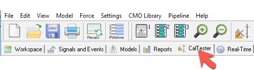
- Switch to CalTester Mode
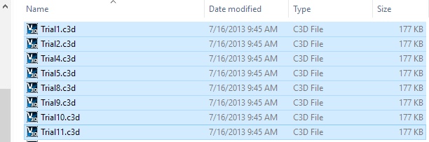
- Load the files from the Examples from the Front Platform of the treadmill.
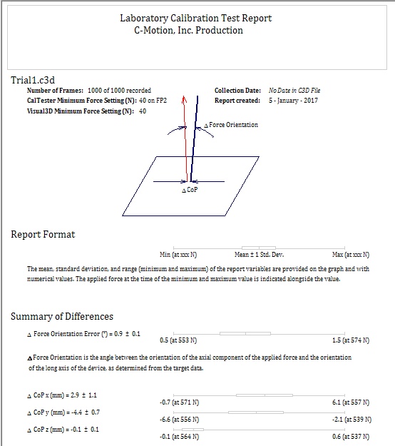
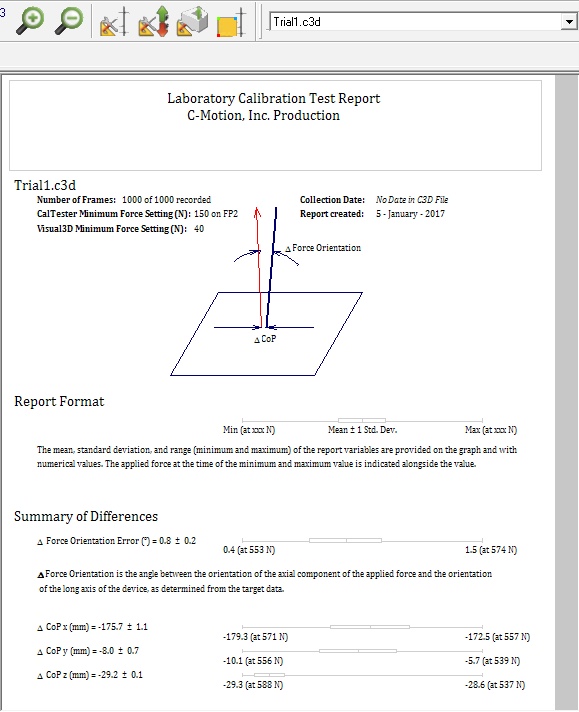
- The report page for Trial1.c3d should be created
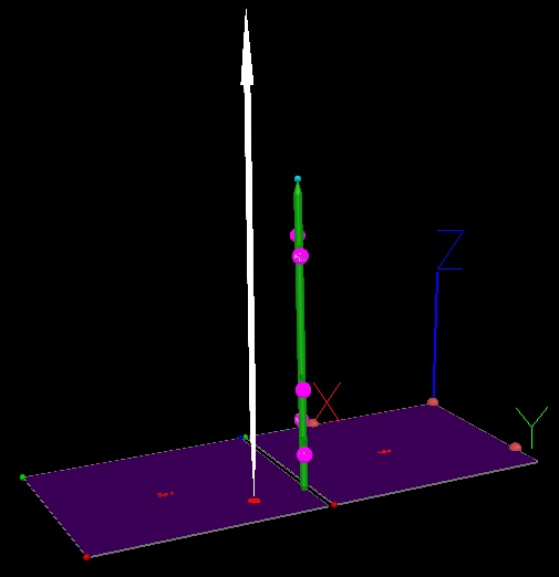
- Note that the results are terrible, which can also be seen in the 3D Viewer
- Click on the Force Platform Locator button
 in order to open the Force Platform Locator dialogue box.
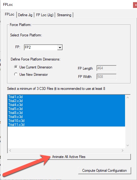
- In the Select Force Platform section, select the Force Plate you wish to locate using the drop down box.
- In the Define Force Platform Dimension section, check that the FP Length and FP Width are correct. If they are, make sure that the Use Current Dimension radio box is selected. If they are not, select Use New Dimension radio box and change the FP Length and FP Width to the correct values.
- Select the button Animate All Files.
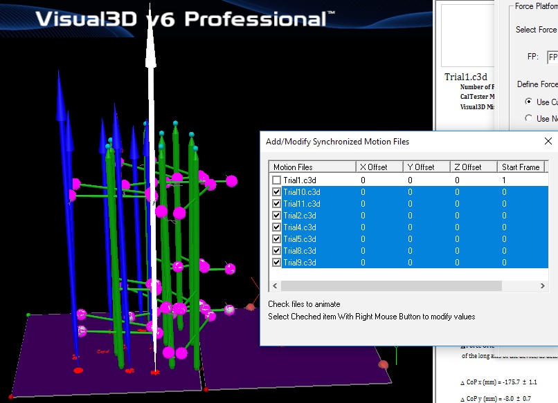
- Notice that all highlighted files are animated simultaneously, and that all files seem to have consistently bad results (as expected in a tutorial)
- Select the button Compute Optimal Configuration.
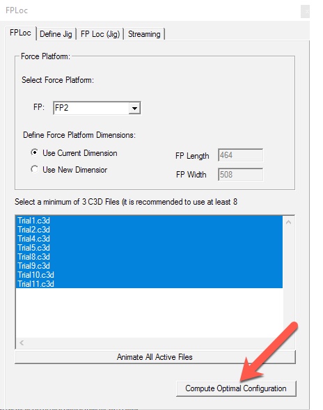
- Wait for Visual3D to calculate the configuration. This may take a few seconds.
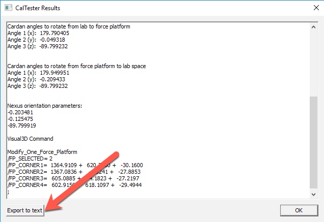
- The CalTester Results window will open and present the following: the output for the force platform, the corrected location (in mm), the force platform center, the rotation matrix (into lab space), the cardan angles to rotate from lab to force platform, the cardan angles to rotate from force platform to lab space, the nexus orientation parameters, and the Visual3D command.


Results (click to expand)
|
A sample of the output that should be created is provided below:
|
- If you wish to save the output you can click on the Export to text button at the bottom left of the results dialogue box.
- In the 3D Viewer you can see that the force platform has moved so that the force vectors are aligned with the CalTester Rod.
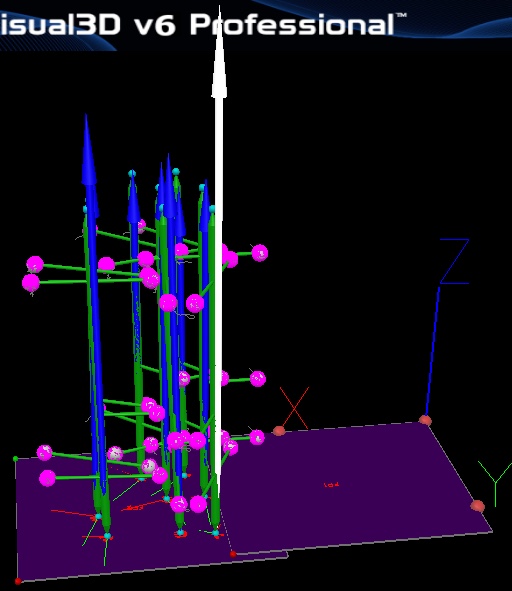
- In the CalTester Report you can see that the errors are now acceptable.