Visual3DServer Documentation
| Language: | English • français • italiano • português • español |
|---|
Introduction
The Visual3DServer has two major components. The shell is the portion that controls the program's graphics and settings. The plugins are the sections that control how the Server connects with the available hardware.
Shell
Connecting
![]()
The "Connect to Hardware" buttons are located on the hardware tabs at the top of the program on the left hand side. There will be one tab for each of the hardware options that you selected when you installed the Server. A blank circle to the left of the name indicates that the hardware is not connected and a green circle indicates that there is a live connection. In the example above the C3D file is connected and the other three are not. Clicking on the circle will either connect or disconnect the hardware depending on its status. Multiple types of hardware can all be connected at the same time.
Record Controls
Near the bottom of the Visual3DServer window are the controls that are used to record and save data to disk.
At the top of the record controls is the file path and the browse button. The file path, where it reads C:/Users/c-motion, tells you where the file you collect is going to be saved. The browse button allows the user to change where the file collected will be saved. To the bottom left is the text field where the file name the file is to be named is specified, in the example it reads static002. Visual3DServer will automatically increase the count at the end of the file name by one. To the bottom right is the timer, in the example it reads 10.00 s. This controls the length of the capture and can be set at any number between 0 and 9,999.99. However, recording for lengthy periods of time requires a computer with sufficient speed. To the far right is the start recording button which is only active when the program is connected to a hardware system.
The collection controls will turn to the above once the data collection is over. The Start Recording button to the far right will change to the Next and Delete buttons. Next will finish saving the file to disk and Delete will permanently remove the file from memory. Both will return the right hand button back to the Start Recording button.
3D-View

|
The first tab to the left, regardless of which hardware plugins have been installed, is the 3-D View tab. This presents a graphical representation of the data being received by the system. It shows what is presented in the 3D view in the plugin tabs with the exception that the 3-D View tab amalgamates the data received from all hardware sources. As such you can see both force and marker data at the same time even if they originate from different hardware systems.
Save 3D View

This button allows you to save what is currently being displayed in the 3D view graphics area. The image can be saved in a number of standard formats, such as .bmp, .ico, .jpeg, .jpg, .pbm, .pgm, .png, .ppm, .tif, .tiff, .wbmp, .xbm, or .xpm. This function is ideal for producing graphics for papers or presentations. Saved images can be edited with 3rd party graphics programs if needed.
Copy 3D View to clipboard

This button allows you to copy what is currently being displayed in the 3D view graphics area to the clipboard. This allows you to paste the image into any program that supports copy and paste. This is useful for working with presentation or graphics editing software.
Reset camera 3D View

This button brings the 3D viewer back to it's beginning position. You may find that having used the rotation, translation, and zooming capabilities of the 3D view you have lost track of where you are in the graphics, which can make returning to a proper view of your data challenging. The reset view button removes this frustration and reorients you.
3D View Preferences

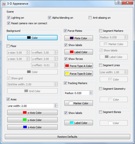
This button allows you to change how the graphics that are presented to you. Changes happen in real time. At the bottom is the "Restore Defaults" button which resets all of the options to their standard setting.
Scene
|
Lighting on - When selected graphics that are suppose to be 3 dimensional have shadows to help simulate shape. When not selected objects are one solid color.
Reset camera view on connect - When this box is selected and you connect or reconnect to hardware the camera view will reset to it's default.
Alpha-blending on - When this box is selected the graphics are slightly transparent and allow you to see what is behind them
Anti-ailiasing on - When this box is selected all the lines in the graphics are smooth. If it is not selected the lines that are not either horizontal or vertical change directions portion by portion.
Background
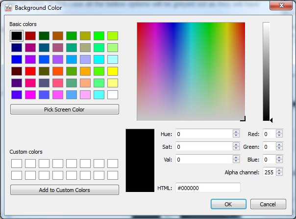
Color - This allows you to change the background color to anyone you chose.
Floor
When the check box next to the floor is not checked the floor will not appear in the 3D View. In this case all the bellow options will be greyed out as they will have no effect if the floor is not present.
X-size - This allows you to customize how many panels the floor is composed of in the x direction. the minimum is 1 and maximum is 100. The default size is 5.00.
Y-size - This allows you to customize how many panels the floor is composed of in the y direction. the minimum is 1 and maximum is 100. The default size is 5.00.
X-offset - This allows you to shift the entire floor along the x-axis either in the positive or negative direction. The maximum value allowed is 100 and the minimum value is -100. The default setting is 3.00.
Y-offset - This allows you to shift the entire floor along the y-axis either in the positive or negative direction. The maximum value allowed is 100 and the minimum value is -100. The default setting is 3.00.
Z-offset - This allows you to shift the entire floor along the z-axis either in the positive or negative direction. The maximum value allowed is 100 and the minimum value is -100. The default setting is -0.01.
Color - This allows you to change the floor color to anyone you chose.
Show grid - This allows you to remove the grid lines from the floor by unchecking the checkbox.
Grid line width - This allows you to change the thickness of the gridlines. The minimum value is 1 and the maximum value is 10. The default width is 2.00.
Grid color - This allows you to change the grid line color to anyone you chose.
Axes
When the check box next to the axis is not checked the axis will not appear in the 3D View. In this case all the bellow options will be greyed out as they will have no effect if the axis is not present.
Line width - This allows you to change the thickness of the axis lines. The minimum value is 1 and the maximum value is 10. The default value is 2.00.
X-Axis Color - This allows you to change the x-axis line color to anyone you chose.
Y-Axis Color - This allows you to change the y-axis line color to anyone you chose.
Z-Axis Color - This allows you to change the z-axis line color to anyone you chose.
Force Plates
When the check box next to the force plates is not checked the force plates will not appear in the 3D View. In this case all the bellow options will be greyed out as they will have no effect if the force plates are not present.
Plate Color - This allows you to change the force plate color to anyone you chose.
Show labels - This allows you to remove the force plate label, (such as FP1, FP2 . . . etc) from the 3D view.
Label Color - This allows you to change the force plate label color to anyone you chose.
Show forces - When checked the forces will be show in the 3D view using arrows.
Force Type A Color - This allows you to change the color of the raw force arrows to anyone you chose.
Force Type B Color - This allows you to change the color of the force structure arrows to anyone you chose.
Tracking Markers
When the check box next to the tracking markers is not checked the tracking markers will not appear in the 3D View. In this case all the bellow options will be greyed out as they will have no effect if the tracking markers are not present.
Radius - This allows you to change the radius of the markers. The maximum value is 0.100 the minimum value is 0.001. The default radius is 0.020.
Marker Color - This allows you to change the color of the marker color to anyone you chose.
Show Labels - This allows you to remove the marker labels from the 3D view.
Label Color - This allows you to change the color of the label to anyone you chose.
Segment Markers
|
When the check box next to the segment markers is not checked the segment markers will not appear in the 3D View. In this case all the bellow options will be greyed out as they will have no effect if the segment markers are not present.
Radius - This allows you to change the radius of the markers. The maximum value is 0.100 the minimum value is 0.001. The default radius is 0.020.
Marker Color - This allows you to change the color of the marker color to anyone you chose.
Show Labels - This allows you to remove the marker labels from the 3D view.
Label Color - This allows you to change the color of the label to anyone you chose.
Segment Lines
When the check box next to the segment lines is not checked the segment lines will not appear in the 3D View. In this case all the bellow options will be greyed out as they will have no effect if the segment lines are not present.
Line Width - This allows you to change the thickness of the segment lines. The minimum value is 1 and the maximum value is 10. The default value is 1.00.
Color - This allows you to change the color of the segment lines to anyone you chose.
Segment Geometry
When the check box next to the segment geometry is not checked the segment geometry will not appear in the 3D View. In this case all the bellow options will be greyed out as they will have no effect if the segment geometry is not present.
Color - This allows you to change the color of the segment geometry to anyone you chose.
Segment Bones
When the check box next to the segment bones is not checked the segment bones will not appear in the 3D View. In this case all the bellow options will be greyed out as they will have no effect if the segment bones are not present.
Color - This allows you to change the color of the segment bones to anyone you chose.
Control Buttons
Located at the bottom of the screen the control buttons effect and provide information on the whole Server.
Pause Display
![]()
The Pause Display button freezes all of the active 3D-view screens. Once paused the Pause Display button will become the Resume Display button. Data continues to stream to and from the server when the 3D-views are paused.
Settings
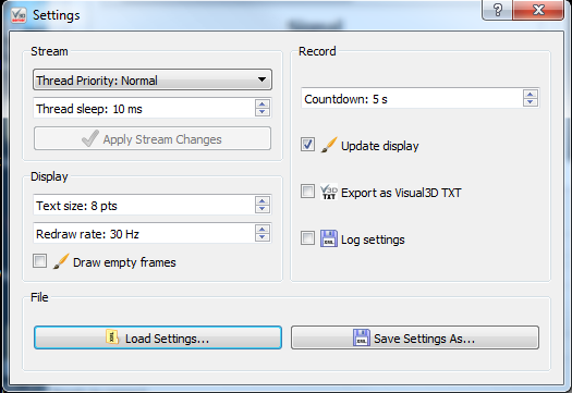
The Settings window, shown on the right, is opened using the Settings button, shown above.
|
Stream
The Stream portion of the settings dialogue allows you to control the data that is coming in such as Thread Priority and Thread Sleep Time.
Thread Priority
The code that acquires frames operates in a separate thread of execution (much like a separate program). Each thread (or program) on a computer has a priority. In fact, if you start the Windows task manager (right click the Task bar at the bottom of the screen) you'll see, under the processes tab, that you can view and set the "priority" of any program. Normal Priority is usually fine for most threads (and programs).
Thread Sleep
The sleep time is how long the capture code waits (in milliseconds) before trying to acquire another frame. This gives other programs on the computer time to perform their tasks. As long as the sleep time is smaller than the camera frequency time (in milliseconds), everything should work. For example OptiTrack cameras running at 100 Hz is equal to 10 milliseconds (1000 / 100). So the thread sleep time should be less than 10 ideally. Values of 1 through 5 are good choices so as to reduce the chances of missing the occasional frame.
If you set the thread priority to very high and the sleep time very low you will get the best capture performance, but the user interface (along with the rest of your computer) might become much less responsive.
It is likely that these features will be either hidden or removed at some point as this level of user control is not that useful now that the frame acquisition code has been refined.
Apply Stream Changes
When you make changes to the Thread Priority or the Thread Sleep the Apply Stream Changes button will become active. You will need to press it in order to apply the changes. This is in place to prevent users from accidentally interrupting their session by inputting an incorrect setting.
Display
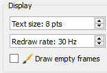
The display portion of the settings dialogue allows you to control the program outputs by personalizing the graphics.
|
Text Size
This allows you to change the text size for all writing in both the Settings dialog and in the main application window. Text size may range between 8 and 16 with the default set at 8.
Redraw Rate
The redraw rate controls at what frequency the graphics on the right hand side of the screen are redrawn. The higher the redraw rate the smoother the movements in the graphics will appear. However, drawing at higher rates takes more of the computer's processing time and, depending on the speed of the computer, may result in frames being dropped. The redraw rate is limited to 1000Hz, for practical purposes the human eye cannot appreciate the difference of a redraw rate above 50 Hz.
Draw Empty Frames
The draw empty frames checkbox tells the program that when the box is checked if there are no new frames when it is time for the graphics to redraw to leave the previous graphics on the screen. If the box is not checked then if there is no new data then graphics will not be drawn. Leaving the checkbox checked will result in smoother graphics however, you will have no visual indication that frames may be missing.
Record
The record portion of the settings dialogue controls record function which allows for signal when recordings begin and end as well as saving preferences.

|
Countdown
The countdown option allows the user to implement a delay between when they push the Start Recording button and when the recording actually begins. This allows a single user to move from the computer to the capture volume before the recording starts.
Update Display
If the update previews checkbox is selected the computer will continue to redraw the graphics while the computer is recording. If this box is selected on a slower computer you may risk dropping frames. However, for fast computers this allows you to see the motions as they are being recorded.
Export as Visual3D TXT
The export as text file checkbox allows you to save a .txt file for each motion capture. The .txt file will contain the values for the position (x and y coordinates), height, and width for each data point, during each frame, for each camera. The .txt files can be opened in programs such as Notepad++.
Log Settings
The log settings checkbox saves a separate .xml file for each motion capture that is recorded. The .xml file contains the details of the settings for both the settings dialog and the main application window.
File
Load Settings
The "Load Settings" button allows you to load an .xml file which holds settings for a specific project.
Save Settings As
The "Save Settings As" button allows you to save your settings as an .xml file so that they can be reused in the future without having to be manually set.
Help
![]()
The "Help" button leads to the Visual3DServer Overview web page should you need to reference this documentation in the future.
About
|
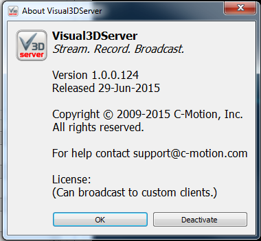
The "About" button opens a window that has details on Visual3DServer including version number, release date, copy right information, support contact information, and if the program has been licensed and is able to broadcast to custom clients. If the Visual3DServer SDK has also be installed the About window also have either the "Deactivate" button or the "Activate" button. Purchasing, installing and activating Visual3DServer allows it to be used to stream to clients other than Visual3D. Deactivating the licence allows users to move the program from one computer to another instead of purchasing another licensing key.
For more information on the difference between the Visual3D real time capabilities and Visual3DServer, click here.
Plugins
Each installed hardware plugin is represented by a tab at the top of the Application window next to the 3-D View tab. Each tab includes controls and displays for managing the corresponding hardware system.
Visual3DServer can receive real-time data from the following hardware systems:
- C3D File
- CEN File
- Myon
- x-io
Specifications for the plugins can be found on the Plugins page.


