Marker Sets
| Language: | English • français • italiano • português • español |
|---|
Visual3D supports almost any marker set, including 6 Degree of Freedom, Helen Hayes/Newinton (e.g." Convential Gait Model"), CODA, and many laboratory in-house systems. Place tracking markers on the segments in strategic and geometrically relevant positions that move only minimally with skin movement. Random placement of markers may result in unusable data You will need two types of markers: calibration markers (for defining the segments) and tracking markers (for computing the movements). Calibration markers can be used for tracking, but be aware that markers placed near the ends of segments (e.g. the lateral knee) are especially susceptible to skin movement artifacts.
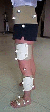
Visual3D interprets all marker sets in a similar fashion. The marker configuration promoted for Visual3D consists of a combination of arrays of markers placed on a rigid surface and markers placed on anatomical landmarks. Visual3D landmarks can also be used instead of physical markers but the user should be aware that landmarks used to define one segment that are created with respect to another segment result in the two segments having less than 6 degrees of freedom each.
Care must be taken to ensure that movement artifact is not produced by the weight of the marker or the marker attachment devices moving relative to the bones (Karlsson and Tranberg, 1999). Broadly speaking, there are four categories of configurations:
- markers mounted on bone pins
- skin mounted markers on specific anatomical landmarks on the segment
- arrays of markers on a rigid surface
- combination of markers on anatomical landmarks and arrays of markers
An array of three-non-collinear markers on a pin that is inserted directly into the bone is often held as the "gold standard" against which other marker systems are held. Clearly, the direct attachment of the markers to the bone could give the most accurate measure of motion of that bone (Fuller et al., 1997; Reinschmidt et al., 1997).
The least accurate marker set would occur when the three individual, non-collinear markers are placed directly on the skin (Fuller et al., 1997; Reinschmidt et al., 1997, Karlsson and Tranberg, 1999). Because the markers would move independently of each other, a great deal of error would be introduced into subsequent calculations. Fuller et al. (1997) reported displacements of the individual markers relative to the bone of up to 20 mm while other studies have reported values up to 40 mm (Reinschmidt et al., 1997). Reinschmidt et al. (1997) reported good agreement between skin and bone markers in knee flexion/extension but a great amount of disagreement in abduction/adduction and internal/external rotation when compared to the respective ranges of motion. The average error relative to the range of motion was 21%, 63% and 70% for flexion/extension, abduction/adduction and internal/external rotation respectively. It should be noted that the motion of skin markers is also task dependent. For motions in which there is an impact transient for example, the motion of the skin-mounted markers was greater than bone markers.
In many instances, researchers have placed the non-collinear markers on a rigid structure and attached the structure to the segment (McClay and Manal, 1999; Manal et al., 2000). Because all of the markers are fixed to a rigid structure, this system has the advantage that the markers cannot move relative to each other. That is, they are not independent of each other. Angeloni et al. (1993) reported that significantly greater displacements were observed in skin mounted markers as opposed to markers mounted on rigid plates. They suggested that markers mounted on plates were preferable to skin mounted markers for both practical and accuracy reasons. Manal et al. (2000) evaluated several configurations of arrays of markers for the tibia and concluded that a marker set consisting of four markers attached to a rigid shell was optimal. It was suggested that such a shell should be placed more distally to avoid the soft tissue of the more proximal portion of the segment. However, rotational deviations of +2 degrees about the mediolateral and anteroposterior axes and +4 degrees about the longitudinal axis occurred even with the optimal marker set.
In several marker sets, the triad of markers on a segment may consist of two markers on anatomical locations and a third marker placed on a rod that projects laterally out from the segment. The marker placed on the rod is used to achieve better 3-D measurement of rotation of the segment about its longitudinal axis. Karlsson and Tranberg (1999) suggested that the inertia of markers placed on rods may dominate over skin movement when measuring faster motions.
Therefore, in deciding the marker configuration to be used it is necessary to be aware of the limitations that can be imposed on the measurement of 3-D coordinates simply as a result of the marker set. Optimally, markers should be placed on a pin inserted into the bone itself. However, this is not always feasible. Consequently, the researcher must decide which of the externally placed marker configurations will be optimal for the task under investigation. Furthermore, the accuracy of measurement from segment to segment and axis to axis is different. It is clear that relatively reliable measures can be made for all segments in terms of flexion/extension movements. However, the secondary axis motions are less reliable, particularly the internal/external rotation about the long axis of the segments.
Basic Rules
Visual3D does not require the user to adopt a special marker configuration. The skeletal model defined in Visual3D has a precise definition that the user can follow to create any number of segments within a model. Following these basic rules allows Visual3D to calculate the 6 degree of freedom pose (position and orientation) of every segment using optimal techniques.
The two basic rules are:
At least 3 tracking markers must be attached to each segment and recorded during the movement trial.
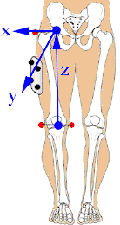
A standing trial identifies four static markers that represent medial and lateral locations at the proximal end of the segment, and the medial and lateral locations at the distal end of the segment.
Useful consequences of these rules.
Consequence 1. Segments to do not have to be part of the human body
Any object can be tracked provided the rules are followed. Those objects that are not part of the primary subject can only be interpreted as Kinematics only segments. At this time, the dynamics of the interactions cannot be quantified within Visual3D. The calculation of Inverse Dynamics based on signals collected from an instrumented handle are currently under development. Assistive devices, such as a cane, can be tracked. External objects such as peg boards can be incorporated into the animation. Segments can be from different bodies allowing the creation of "models" of multiple subjects in the scene. A robot can be tracked that is interacting with the user (e.g. a Phantom robot).
Consequence 2.
Segments of the body can be defined with more than one segment coordinate system. Visual3D assumes that segments are not twisted about their longitudinal axis. If there is a "torsion" of the bone, such that the proximal and distal joints are rotated relative to each other, it might be useful to create one coordinate system for defining the proximal joint angle and a rotated coordinate system for defining the distal joint angle. Note that only one of these segments can be considered part of the inverse dynamics calculation, the other segment(s) must be a Kinematics only segment. Exceptions to these rules provide flexibility.
Exception 1. Common targets are allowed.
Visual3D allows the user to define the same tracking marker to adjacent segments. For example, a marker placed on the lateral aspect of the knee may be used to track the thigh and the shank. Under these conditions the Visual3D model no longer has 6 independent degrees of freedom.
Exception 2. Using a movement trial as a static trial
Visual3D allows the user to use the movement trial as both a movement trial and a standing trial (selecting one frame for processing). The movement trial must have the four static markers required to define a segment.
Exception 3. Anatomical measurements can be used to create "virtual" static markers
Visual3D (in Model Builder Mode) allows the user to create virtual markers. These virtual markers are defined as offsets with respect to an existing marker. These offsets are commonly determined from anatomical measurements on the subject.
Exception 4.
A 3D digitizer can be used to create "virtual" static markers Some laboratories use a digitizing wand to locate anatomical landmarks. These landmarks are typically collected in the laboratory coordinate system (defined by the video cameras). The user can specify the digitized values as offsets from the LAB segment in model builder mode. Note that these values can also be entered into the ASCII model file.
Exception 5. Defining "virtual" tracking markers.
Tracking markers are assumed to exist in all movement trials. The user can create plug-ins, or import data, for which "virtual" tracking markers are calculated. Visual3D uses this approach to create tracking markers that represent the virtual joint centers for Helen Hayes marker sets.
Note that the Helen Hayes marker sets typically have two tracking markers per segment and the proximal joint center. Because the proximal joint center has been calculated using information from the proximal segment, the Helen Hayes marker set does not have 6 degrees of freedom. This dependence on the proximal segment causes errors to propogate from segment to segment (e.g. errors in the hip joint center cause errors in determining the pose of the foot).
Marker Placement
Visual3D interprets all marker sets in a similar fashion. The marker configuration promoted for Visual3D consists of a combination of arrays of markers placed on a rigid surface and markers placed on anatomical landmarks.

