3D Animation Viewer
Changing the data file being animated
![]()
Visual3D pipeline commands and animations use the ACTIVE_FILE. The user can select the ACTIVE FILE using the data file combo box.
3D Viewer Animation Controls
Roll your mouse over the image below for a brief introduction to the various parts of the Visual3D™ Animation Control .

The animation controls provide functions that are similar to standard video controls.
Controlling the 3D animation window.
Controlling the position and orientation of the camera in the 3D viewer.
- The left mouse button is used to modify the orientation of the 3D view of the scene. Holding down the left mouse button and moving the mouse vertically rotates the scene about the horizontal axis of the scene view, moving the mouse horizontally rotates the scene about an axis parallel to gravity.
- The right mouse button is used to modify the scaling of the scene. Holding down the right mouse button and moving the mouse outward moves the camera closer to the center of the scene (increases the size of the image displayed).
- Holding down the center mouse button (on a three-button mouse), or both the left mouse button and right mouse buttons together, allows the user to shift (translate) the scene from side to side and up or down.
Setting the sensitivity of the mouse movements

The sensitivity of the 3D transformations of the scene relative to the physical movement of the mouse is determined by several factors. The user does not need to figure out these factors but can modify the effective sensitivity by selecting "Modify the mouse rotation sensitivity" under the "Properties" menu and determining the preferred sensitivity by trial and error. The sensitivity value is saved to the Registry.
- Controls what items are displayed in the 3D viewer.
- Color a segment or a muscle based on a color lookup table and a signal
Animating Multiple C3D Files
Select the following file menu option.

The following dialog will appear allowing you to select the files to be displayed simultaneously. Note that the currently active motion file will also be displayed.

An example of the resulting animation is as follows:

Color Map Signal To Muscle
Color a segment or a muscle based on a color lookup table and a signal
Under the model menu item, select Color Item With Signal

Select the segment (or muscle) that is to be colored.
Select the signal
Pipeline Command: Map_Signal_To_Muscle
Map a Signal to a Muscle. The range of the signal is mapped to the default look up table that determines the color that the muscle will be rendered in the 3D animation viewer for a given value of the signal.
| Map_Signal_To_Muscle | |
| /Calibration_File= | The name of the Link Model (Standing Trial) |
| /Muscle_Names= | The type of the muscle to be colored by a signal |
| /Signal_Types= | The type of signal to be evaluated |
| /Signal_Names= | The names of the signals to be evaluated |
| /Signal_Folder= | The name of the signal folder |
| /Component= | (X, Y, Z, or Magnitude)The component of the signal used to color the muscle. |
Camera Tracking
(Have the camera track a segment in the 3D viewer rather than stay stationary in the laboratory.)
The default animation viewer allows the user to interactively set the position and orientation of the camera. The scene stays stationary. If the motion capture volume is quite large and the segment of interest is quite specific (e.g. focusing on the pelvis), it can be a nuisance to follow the subject through the volume.
- Select the position and orientation of the camera with respect to the laboratory coordinate system
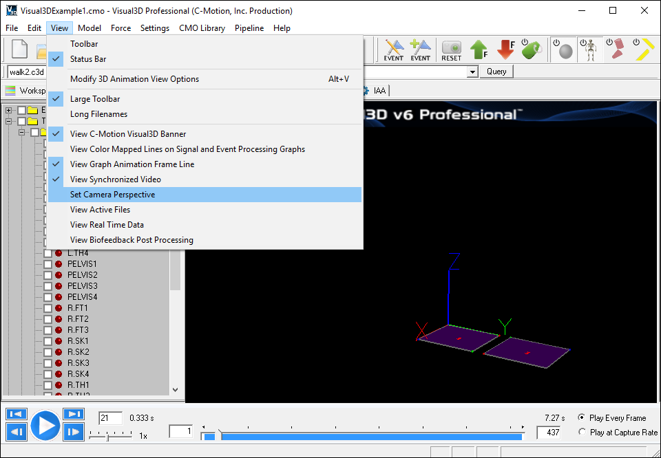
- Select Set Camera Perspective from the View Menu
- Save the Current Camera Perspective
- Overwrite the existing perspective
- Select the pelvis segment and select Move Camera to Track Segment CG
- Play the animation. When the pelvis segment is in view the camera will be focused on the segment. The scene will shift so that the pelvis segments remains in view.


Modify the Properties of the Animated Markers
You can modify the size of the targets, landmarks, and joints in three ways.
Marker Size
First, by defining the default size of all markers


Second, by scaling the size in the Data Tree. Select a signal in the data tree using the right mouse button, then select the item "Draw Target Size"

Third, by scaling the size by selecting "Draw Target Properties"


Fourth, use a pipeline command. Note that this uses the same dialog as above.
- Set_Animation_Draw_Properties
- /SIGNAL_TYPES=
- ! /SIGNAL_FOLDER=ORIGINAL
- ! /SIGNAL_NAMES=
- ! /TARGET_SIZE=NORMAL
- ! /OVERRIDE_TARGET_COLOR=TRUE
- /TARGET_COLOR=#80FF80
- /DRAW_TRAIL=TRUE
- ! /OVERRIDE_TRAIL_COLOR=TRUE
- /TRAIL_COLOR=#FFFF80
- /TRAIL_ALL_FRAMES=TRUE
- ! /TRAIL_BEHIND=
- ! /TRAIL_AHEAD=
- ;
Marker Colors
Motion Capture marker data are displayed in the data tree with four elements (z,y,z, residual).
The residual value is a result value from the 3D tracking software. In the C3D file format:
- a residual value less than zero indicates that the data is unreliable
- a residual value equal to 0 indicates that the data were processed prior to get into Visual3D or the original data processing was manual or unknown.
The default animation view displays the markers as grey spheres.
- To distinguish the "ORIGINAL" markers that have been processed (e.g. a residual value equal to zero) Visual3D draws them in red.
- If the user selects to color the markers by residual, the color of the marker changes from green (near zero residual) to yellow.
Segment Primitives
Segment Primitives can be a useful tool in visualizing the position and orientation of segments in relation to each other. Segment Primitives can either be drawn using the pipeline, or by using the Draw Segment Primitives Dialog, both methods are described here
Example 3D Viewer 1
Draw a Line between 2 Markers
As of version 4.0 Visual3D does not provide the capability to draw a simple line in the 3D viewer. If only a few lines are being drawn, and the movement trial has been assigned to a Visual3D model, it is possible to create a virtual muscle. The virtual muscle is displayed as a small cylinder in the 3D viewer.
In the following example, draw a line between markers S1 and S2, and another line between markers L1 and L2.
Step 1- Create landmarks
Visual3D muscles are connections between landmarks, so create landmarks coincident with the 4 markers.

Create similar landmarks for S2, L1, & L2
Step 2 Create Muscles
Switch to the Muscles Tab in Model Builder Mode.
Enter the name S1S2 into the Name Edit Box.
Select Create Muscle.

Step 3 Add Landmarks to Muscle Definition
Select the landmark in the bottom combo box below
select Append Landmark.
Do this for each of the two landmarks.

Now do the same for a muscle names L1L2 comprised of landmarks L_L1 & L_L2
Step 4 Check the view option to display muscles
