There are many options for controlling the default settings for Visual3D and for controlling the viewing options. The Program Options dialog can be accessed from the Edit Menu item

There are 3 TAB dialogs in the program options property pages.
Default Folders
3D Animation Options
3D View Options
Default Folders
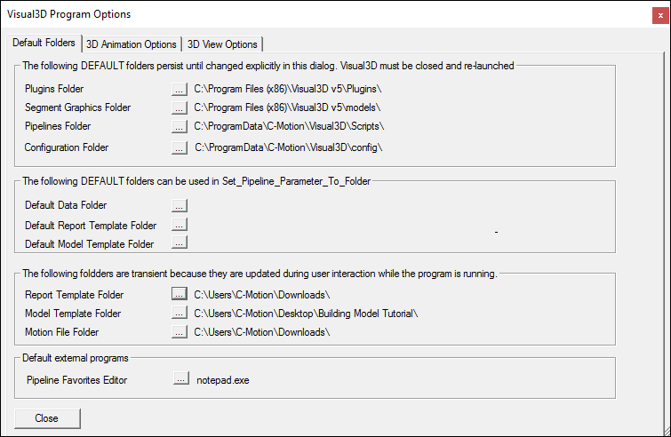
Visual3D has 3 categories of folders.
- Folders that are identified when Visual3D is launched, and which are rarely modified.
- Default folders that are convenient for may pipelines that specify generic folders
- Folders that change dynamically as the pipeline executes.
| Default_Folders
|
| Plugin Folder |
Visual3D searches this folder for Visual3D Plugins. These plugins may be processing plugins that will appear in the list of Pipeline commands, or they may be Real_Time plugins that will appear in the options for Real-Time Streaming |
| Segment Graphics Folder |
The animation models associated with the model segments are stored in. If no path to an object file is selected in the Segment Properties dialog, Visual3D searches hear for the file. |
| Script Repository Folder |
Default folder for Pipelines. Used mainly for the Pipeline Favorites. |
| VISUAL3D_DEFAULT_PIPELINE_FOLDER |
| Default Data Folder |
The pipeline commands may refer to the default data folder as
VISUAL3D_DEFAULT_FOLDER
OR |
| VISUAL3D_DEFAULT_DATA_FOLDER |
| Default Report Template Folder |
Current default FOLDER for the report template. |
| VISUAL3D_DEFAULT_REPORT_FOLDER |
| Default Model Template Folder |
Current default FOLDER for the standing trial. |
| VISUAL3D_DEFAULT_MODEL_FOLDER |
| Motion File Folder |
Current FOLDER for the motion trial. Reset every time a movement file is opened. |
| Report Template Folder |
Current FOLDER for the report template. Reset every time a Report Template is opened. |
| Model Template Folder |
Current default FOLDER for the standing trial. Reset every time a Hybrid Model is created. |
Example:
- Set_Pipeline_Parameter_To_Folder_Path
- /PARAMETER_NAME=DATA_FOLDER
- /PARAMETER_VALUE=VISUAL3D_DEFAULT_FOLDER
- ;
- Set_Pipeline_Parameter_To_Folder_Path
- /PARAMETER_NAME=MODEL_FOLDER
- /PARAMETER_VALUE=VISUAL3D_DEFAULT_MODEL_FOLDER
- ;
To use this parameter in a command
- !Open all of the c3d files in a folder within the default folder
- File_Open
- /File_Name= ::DATA_FOLDER&/SUBJECT1/*walk*.c3d
- ;
- ! Create a hybrid model and assign a model template from the default model folder
- Create_Hybrid_Model
- /CALIBRATION_FILE=::DATA_FOLDER&/SUBJECT1/*static.c3d
- ;
- Apply_Model_Template
- /MODEL_TEMPLATE=::MODEL_FOLDER&GaitModel.mdh
- /CALIBRATION_FILE=::DATA_FOLDER&/SUBJECT1/*static.c3d
- ;
Note that there is a pipeline command to set these options from a pipeline. This can be useful for setting the folders automatically for the user.
- Set_Default_Folders
- ! /PLUGINS=
- ! /SEGMENT_GRAPHICS=
- ! /PIPELINE=
- ! /REPORT_TEMPLATE=
- ! /MODEL_TEMPLATE=
- ! /MOTION_FILE=
- ! /DEFAULT_DATA=
- ! /CMO_LIBRARY_PATH=
- ! /DEFAULT_REPORT_TEMPLATE=
- ! /DEFAULT_MODEL_TEMPLATE=
- ;
|
|
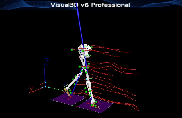
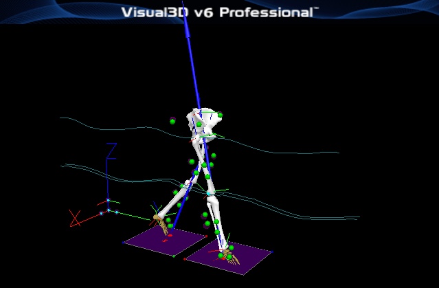
The Visual3D animation display, pictured below, allows you to visualize the movement of target markers, model segments (if defined), and other time-dependent phenomena such as ground reaction force (GRF) measured by force platforms.
Visual3D’s extensive animation capabilities allow you to choose which of many elements are included in the display. The illustration shows a typical combination: global coordinate system (GCS) axes, force platforms, instantaneous GRF vector and butterfly showing how the GRF evolves through time, target markers, and the instantaneous pose of the model (represented in this case by the major bone structures corresponding to each of the modeled body segments). You can interact with the animation display to zoom, pan, and rotate it to any perspective you choose.
Note that the skeleton (representing the model) is the only part of the animation display pictured above, which will not appear if you have not yet associated the movement trial with a model. If all you do is open one movement trial, you can watch the markers move through space, observe their relationship to the position of any force platforms and the GRF they measure. This alone is a very useful tool for data quality control—if the animation doesn’t look right, your motion-capture data may be invalid.
The 3D Animation Viewer is based on the OpenGL Graphics Library.
3D Animation Options

Define the sensitivity of the mouse; e.g. the responsiveness of the mouse in the 3D viewer.
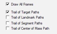
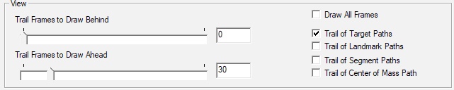
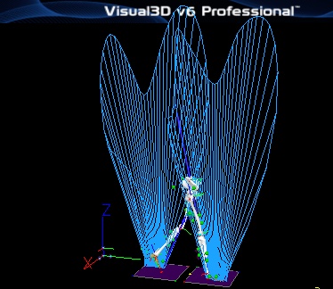
The trail of markers, landmarks, or segments (including the length of the trail in frames) can be set explicitly.
| Draw Trajectory Trail of Targets
|
|


|
| Draw Trajectory Trail of Landmarks
|
|

|
| Draw Trajectory Trail of Segments
|
|
Draw a trajectory trail that follows the Origin (e.g. Proximal end) of the segments


|
| Draw Trajectory Trail of Model Center of Mass
|
|
Note that the trail will only be drawn if the COM is drawn


|
3D View Options

This property pages contains a number of toggle settings for different view options in the animation window.
| 3D View Options
|
| Force Platforms
|
|
Toggles the visibility of the force platforms
|
| Ground Reaction Force Butterfly
|
|
Toggles the visibility of the ground reaction force butterfly.
|
| Ground Reaction Force Vector
|
|
Toggles the visibility of the ground reaction force vector.
|
| Ground Reaction Force COP
|
|
Toggles the visibility of the ground reaction force Center of Pressure.
|
| Ground Reaction Force Free Moment |
Toggles the visibility of the ground reaction force Free Moment. |
| *Segment Assigned (Custom/Combined) |
Displays Assigned Forces. |
| Force Structures/Projected Forces |
Displays Force Structures. |
| View Assigned Force Segments |
Colors all segments that have been assigned to a force. |
| Lab/Floor |
Toggles the visibility of the laboratory and floor. |
| Lab Axes |
Toggles drawing the laboratory coordinate system axes. |
| Lab Axes in Model Builder |
Toggles drawing the laboratory coordinate system axes in Model Builder Mode. |
| Background Black/White |
Draws the 3D animation with either a black or white background. |
| Targets |
Toggles drawing of targets. |
| Color Targets by Residual |
Color Targets by the magnitude of the Residual component. |
| Landmarks |
Toggles drawing of Landmarks. |
| Joints |
Toggles drawing the "Joints" used for the Inverse Dynamics. |
| Local Targets (in LCS) |
Toggles drawing the expected location of the markers as defined by the model. |
| Model Center of Mass |
Toggles drawing the Center of Mass of the Model. |
| Muscles |
Toggles drawing Muscles. Muscles can be drawn as lines or cylinders. |
| Kinetic Segments |
Toggles drawing Kinetic Segments. |
| Kinematic Only Segments |
Toggles drawing Kinematic Only Segments. |
| Display Segment Colors |
Toggles the color of segment based on an assigned signal. |
| Display Segment Inertial Geometry |
Toggles drawing the Segment Geometry. |
| Segments as Stick Figures |
Toggles drawing Kinetic Segments as Stick Figures. |
| Kinematic Only Segments as Stick Figures |
Toggles drawing Kinematic Only Segments as Stick Figures. |
| Segment Coordinate System Axes |
Toggles the visibility of the SCS. Specifies the location to draw the axis as origin or center of mass |
|
|
Segment Colorization
It is possible to color a segment model or a muscle object based on a signal value.
| Segment Colorization (more...)
|
|
A right mouse click in the animation window will cause the following popup to appear. Select Map Segment Color to a Signal Value
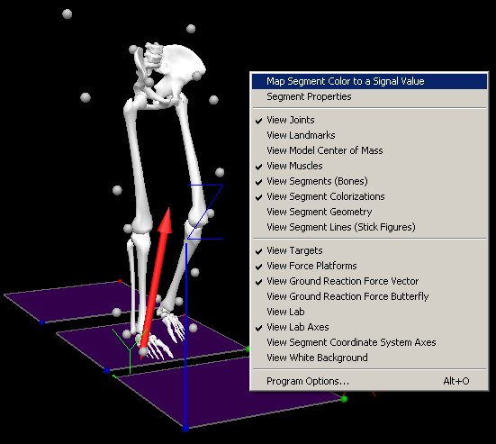
the following dialog allows the selection of a Visual3D model object and the associated signal

In the above dialog the magnitude of the Right Hip Power signal is used to color the Right Thigh Segment. Note that it is important to select the Apply Colorization button after the segment and signal have been selected.

The resulting snapshot from the animation shows the colored right thigh.
|
|
Target Colorization
The motion capture markers are colored based on the TARGET residual value.
| Target Colorization (more...)
|
|
Residual= 0 => Red
Maximum Residual in the file => Yellow
Minimum Residual in the file => Green

Note that if the TARGETS have been processed, the color of the markers will always be green because the residual has no meaning for a PROCESSED signal.

Note that an exception is when the option to Use ProcessTargets for Model/Segment/LinkModeBased Items is unselected because this results in the ORIGINAL signals being used for the animation as well as the computations.
|
|


