Defining a Functional Joint
The properties of the functional joint are defined in the Model Builder : Landmarks : Functional Tab
Step 1. Switch to the Landmarks Tab in Model Builder Mode
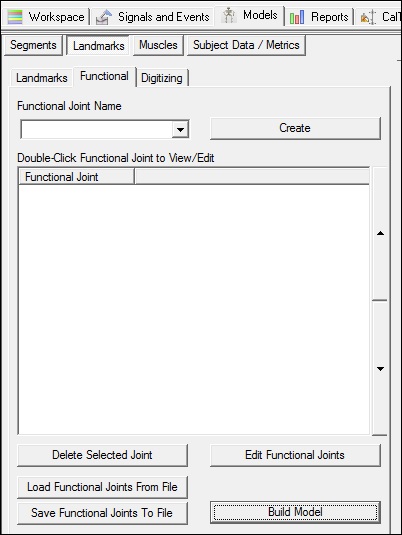
The definition of the functional joints can be saved in an INI file for future use, but it is more common to simply save the Model Template because the functional joint definitions (and digitized point definitions) will automatically be saved to the template. The Visual3D template will actually contain two versions of the functional joints. The first is the actual definition, and the second is the resulting explicit value that results from the functional joint computation. This second landmark is the one that is displayed in the viewer and can be used to define a segment or other landmarks.
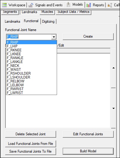
Step 2. Select one of the default landmark definitions from the combo box and create.
Alternatively, you can specify a custom landmark name.
Note that you can save and load functional joint definitions to a file for future use.
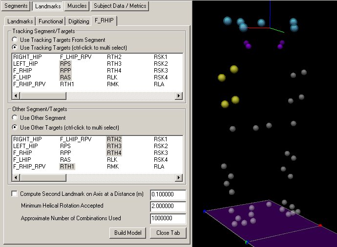
Step 3. Assign the markers/segments for the two segments surrounding the joint
The landmark will be created relative to the tracking segments/targets. For example, if you look at the definition of the landmark that is created after computing the functional joint, it will reference these segments/targets.
The other segment/targets refers to the segment that is moving relative to the Tracking segments.
Note that the Tracking Targets are colored blue in the viewer and the Other Targets are colored yellow.
Originally, the Tracking was referred to as the Reference
There are 3 options available.
- Compute a second landmark that lies on the same axis as the joint computed. This is useful for joints that have only one degree of freedom because the functional joint in these cases can not be computed accurately.
- The minimum helical rotation is related to the algorithm and causes Visual3D to consider only a collection of postures in which the rotation from one posture to another posture is greater than the specified value.
- The algorithm uses all combinations of 3 frames of data in the selected range of frames. This can lead to an inordinate number of possible computations, which will slow the computation. The user can have Visual3D select randomly a restricted number of 3 frames of data
Which targets/segments are actually used in the computation?
Regardless of whether the user selects Targets or Segments, Visual3D creates a technical coordinate system (TCS) to represent each segment for the computations. This is done to ensure that a segment exists because it is possible that the segment definition depends on the functional joint being computed.
Visual3D chooses the three markers (from however many were selected) to be used for the TCS definition. Three markers define the vertices of a triangle. Visual3D searches for the triangle with the largest area, then uses these 3 targets. Visual3D then searches for the two vertices of the three selected that are the farthest apart, and these become the proximal and distal end of virtual segment from which the TCS is defined. The TCS is tracked, however, with all of the Targets that were selected.
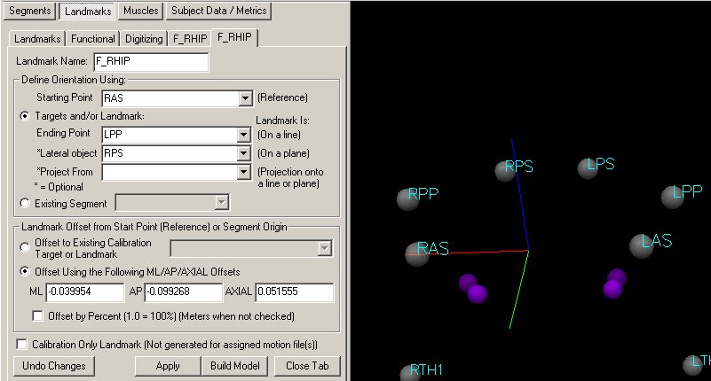
If the resulting landmark is defined relative to Targets (e.g. not to a segment), Visual3D uses the three markers that made up the TCS.
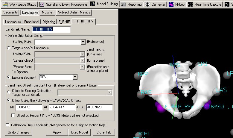
If the resulting landmark is defined relative to a segment, Visual3D transforms the landmark from the TCS into the Segment Coordinate System.
In this case, Visual3D elected to define the landmark relative to RAS, LPP, and RPS of the possible 6 Targets used for tracking the segment.
The same landmark can be defined relative to the pelvis segment rather than to markers.
If you have created the landmark for use in defining segments (e.g. calibration only), it doesn't really matter whether you define the landmark relative to segments or landmarks.
If you have created the landmark and would like to use it for tracking, it is advisable to define the landmark relative to a segment.
