Inverse Kinematics: Define a Model
The difference between the traditional Visual3d 6 degree of freedom model and the Global_Optimization (IK) model is that constraints can be added between segments that restrict the relative motion between the segments. This is accomplished by creating one or more IK chains.
IK chains are created in Visual3D using the IK Constraints tab in the Model builder portion of Visual3d. Prior to creating an IK chain all of this segments that are to be included in the chain must already be defined by in the Segments tab of the Visual3D Model builder.
Inverse Kinematic Chains
All IK chains must start with a root segment. By definition a root segment is a segment that has the Visual3d LAB coordinate system as a parent segment.
Create the Pelvis as a root segment in the IK chain (Remember to select the Add button to add it to the chain)
If no other segments are added to the chain, Visual3D will recognize that the chain is one segment and the 6 DOF algorithm will be used.
In general the root segment will be connected to the LAB with six degrees of freedom however this is not required. (For example if the pelvis were to serve as the root segment in an IK chain you could eliminate pelvic tilt, obliquity and rotation by making the connection between the pelvis and ground such that only translation was allowed.)
Once a root is added the remainder of the IK chain can be built. Segments are added to the IK chain by specifying the segment name and the name of its parents (The parent is the next segment back along that path to the root segment and must already be part of an IK chain).
Constraints, Mobilizers and Degrees of Freedom
When building the IK model the user actually specifies the motion that is permitted between two segments rather than the constraints at the joint. For example to create a spherical joint at the hip the user would specify that right thigh (RTH) is connected to its parent (RPV) with three rotational mobilizers..
One important note is that currently Visual3d does not support any "FIXED" joints. If a segment is included in the IK chain it must have at least one mobilize between itself and its parent segment.
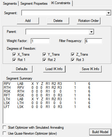
The above image shows the IK chain configuration obtained by selecting the "Defaults Button".
Note that the pelvis is the only segment with 6 degrees of freedom (e.g. 6 mobilizers) and is therefore the root segment of the chain.
- The thighs are ball joints (3 rotational mobilizers)
- the knee is pin joint (1 rotational mobilize)
- the ankle is a universal joint (2 rotational mobilizers).
The Visual3D IK model
The Visual3D IK model is designed to be flexible but a few important features should be kept in mind:
- When a segment is added to the IK chain both the segment and the parent segment must already have been defined in the Visual3d model.
- Following the nomenclature of the NIH Center for Biomedical Computation (SIMBIOS), the permitted motion between two linked segments are referred to as mobilizers. (See the OpenSim documentation at http://simtk.org/home/opensim for details on the term mobilizers.)
- When a segment is added to the IK chain with less than three translational mobilizers (one or more translational constraints) the location of the joint between the segment and the parent is assumed to be located at the segment’s origin.
- Each segment can have only one parent; however a segment can be a parent to more than one child. (For example the right thigh (RTH) might have the Pelvis (RPV) as it’s parent and the RPV might also serve as a parent for the left thigh (LTH)).
- The user can define an IK model that has more than one root segment. (For example the user might want to track the pelvis using the traditional Visual3d 6DOF method but use two separate IK chains for both the left and right lower limbs. In this case both the RTH and LTH should be connected to the LAB as root segments
An example of an IK with two root segments (RTH and LTH). Note the Pelvis (RPV) is not included in the IK chain and thus its position and orientation would be found using the standard Visual3d 6 DoF method
Minimum number of target require to track a segment
Because the IK model adds constraints it becomes possible to track a segment using less than three targets. Currently Visual3d uses the recommendation of Yeadon (1984, Ph.D. dissertation Loughborough University of Technology, Loughborough, England) to determine the number of targets require to track a segment:
- If a segment is connected to its parent using 3 rotational mobilizers but no translation mobilizers (a ball joint) the minimum of targets required to track the segment is reduced to two.
- If a segment is connected to its parent using 2 rotational mobilizers but no translation mobilizers (a universal joint) the minimum of targets required to track the segment is reduced to two.
- If a segment is connected to its parent using 1 rotational mobilizers but no translation mobilizers (a pin joint) the minimum of targets required to track the segment is reduced to one.
- Currently, for all other combinations of rotational and translational mobilizers the minimum of targets required to track the segment remains three.
Selecting the direction of rotation for each of the rotation mobilizes
Each segment in the Visual3d IK model can have between zero and three rotational mobilizers. In the IK Constrainys tab the rotational mobilizers are labeled:
- "Rot 1", "Rot 2" and "Rot 3"
These rotations are not given an X, Y or Z in their labels because the direction of the rotations can be customized by the user.
To set the direction of rotations the users selects the "Rotation Order" button within IK Constraints tab. Once this button is pressed a dialog will appear. This dialog lets the user specify the direction of the axes of rotation for the rotational mobilizers. The user is expected to enter the axes as unit vectors; however after the user selects the "OK" button Visual3d will check (and normalize if necessary) the axes to guarantee they are unit vectors.
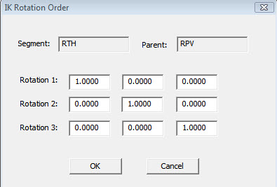
A sample IK rotation order dialog. The unit vectors in this example indicate that the rotation of the RTH with respect to RPV will be given by an X, Y and Z rotation sequence.
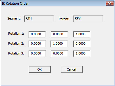
In this Figure we see that Rotation 1 is specified as an X rotation, Rotation 2 is about a Y axis and Rotation 3 is about a Z. This indicates that the rotation of the RTH with respect to RPV will be given by an X, Y and Z rotation sequence. If the user wanted to solve an IK model with a Z,Y,Z (which might be more conventional at the shoulder) the user could specify the directions of the rotations as follows:
A sample IK rotation order dialog. The unit vectors in this example indicate that the rotation of the RAR with respect to RTA will be given by an Z, Y and Z rotation sequence.
Segment filter frequency
When a segment is added to the IK model the user specifies the parent segment and the set of mobilizers connecting the segment to its parent. For each video frame Visual3d will find the set of mobilizers that minimize equation 3 (Section 1.) The solution for equation will have frame to frame noise associated with it and thus the user can low-pass filter the mobilizers associated with any segment. The user can specify different filter cut-off frequencies for different segments. For example in Figure 3, the user has selected to filter the rotations between the left foot (LFT) and left shank (LSK) using a filter cutoff frequency of 6 Hz. (The default cutoff frequency for all segments is 0.0 Hz, which is equivalent to no filtering.)
Segment Weight
When creating an IK chain the user may want to make sure that certain segments follow the tracking targets with a higher degree of accuracy then other segments. For example, the user may want to assure that the distance between the foot (RFT or LFT) and the floor (or force patforms if available) remains similar to the values that would be obtained using the tradition Visual3d 6 DoF method. To help with this situation Visual3d lets the user add a weight factor for the mobilizers associated with each segment. (The default weighting factor for all segments is 1.0). Adding weight factors effectively changes equation 3 to:
1nknimPi- TqAi- O(q)2 (4)
where n is the number of segments in the IK chain. kn Is the weight factor for the mobilizers associated with the segment and m is the number of targets used to track that segment.
Saving IK Models
The Visual3d lets the user add default IK segment properties (including their default parent and mobilizers) for the following segments: RPV, RTA, RTH, RSK, RFT, LTH, LSK, LFT, RAR, RFA, RHA, LAR, LFA and LHA. To load the default IK segment properties the user selects the Defaults button from the IK Constraints tab. However for a default segment to be added to the IK chain both the segment and it expected parent must be present in the Visual3d model.
Once an IK model had been built in the IK Constraints tab, all the information contained for the IK model can be written to a file so it can used to for future motion capture sessions. To save the properties of an IK chain the users selected the "Save IK info" button from the IK Constraints tab. The user will be prompted for the name of the output IK file. The default file extension is "vik". The vik file is an ACII file which fully specifies all the properties of an IK model.
The IK information is considered part of the model and thus it will also be saved with the model template when the user selects the "Save Model Template File" button in the Models program tab.
The IK information will have a separate Visual3d command (IK_DEGREES_OF_FREEDOM)
for each segment in the IK chain. The IK_DEGREES_OF_FREEDOM command has the following parameters:
- /Calibration File – Name of the model for the model calibration
- /Segment_Name – Name of the segment being added to the IK chain
- /Parent_Name – Name of the parent segment. (The parent is the segment the takes the segment back toward the root.)
- /Translation_X – indicates if an X translational mobilizer will be added for the segment
- /Translation_Y – indicates if an Y translational mobilizer will be added for the segment
- /Translation_Z – indicates if an Z translational mobilizer will be added for the segment
- /Rotation_1 – The first rotational mobilizer to be added for the segment
- /Rotation_1_Direction – The unit vector specifying the direction of the first rotational mobilizer
- /Rotation_2 – The first rotational mobilizer to be added for the segment
- /Rotation_2_Direction – The unit vector specifying the direction of the first rotational mobilizer
- /Rotation_2 – The first rotational mobilizer to be added for the segment
- /Rotation_2_Direction – The unit vector specifying the direction of the first rotational mobilize
- / Weight_factor – the weight factor for segment mobilizers in equation 4.
- /Filter_Frequency – low pass cutoff frequency for the segments mobilizers (see Section 2.7)/
Fit Subject Cal to IK Model
When “Fit Subject Cal to IK Model” is checked, the following steps occur:
- The standard segment coordinate systems are created during subject calibration just as they would be in the Visual3d 6 degree of freedom model.
- The location of the tracking targets (averages during the subject calibration) are then computed and transformed into the segment coordinate systems defined in step 1. (This is also done in a Visual3d 6 degree of freedom model.)
- Visual3d then grabs the IK constraints you specify, the segment coordinate system target locations from step 2 and the average lab coordinate of the targets in the subject calibration and input then into an IK optimization in order to find the values of the joint angles that best fit the subject calibration target data under the specified joint constraints.
- The joint angles computed in step 3 and are then used with the specified IK joint constraints to build a new subject calibration model that meets the joint constraints.
- Once the new constrained subject calibration model is built in step 4, the lab coordinates of the tracking targets are then transformed to in the new model’s segment coordinate systems to get a set of new fixed segment coordinate system location for each tracking targets. These new fixed segments coordinates will then be used as input to the IK during the movement trials.
Advantage to fit subject Cal to IK
If your static pose completed complies with the constraints then checking the “Fit Subject Cal to IK Model” will not actually do anything so there should be no advantage to checking this box.


