Knee Alignment Device
| Language: | English • français • italiano • português • español |
|---|
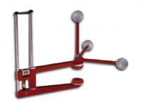
The Knee Alignment Device (KAD) is manufactured by Motion Lab Systems and is described here. The KAD is used to assist in defining the frontal plane of the thigh segment. It is manufactured by Motion Lab Systems to precise definition (5.66 inches or 0.143764 meters between markers). The markers that are provided with the KAD have 24.8 mm markers attached. The KAD is used in the standing trial, and the origin of the KAD is replaced by a marker on the lateral knee located at the intersection of the 3 posts.
Marker Diameter
Many laboratories have taken to replacing the 24.8 mm markers with smaller markers, in an erroneous assumption that it would be a good idea to have all markers used on the body and the KAD to be the same size. This actually introduces an error in the assumptions of how the KAD is used. If this is done, the user must be careful to accommodate this change to the original assumptions. The marker diameter is actually used to define the distance from the "origin" of the KAD (where the arms meet) to the pad which touches the knee. The image to the right from Schache, et. al.[1], which describes the diameter value.
In the KAD distributed by Motion Lab Systems, this diameter matches that of the markers on the original KAD (24.8 mm). How the diameter value is used, is further described in this power point.
Tutorial
To follow along with the tutorial, you can download the KAD_Example.zip file. This file contains:
- Sub01_Static01.c3d - a standing trial which can be used with the example
- KAD.mdh - an example model template with a KAD created for the right side
- Sample_KAD.cmo - a CMO file with a KAD created for the right & left sides
The standing trial
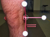
The KAD is placed on the subject at the knee during the static standing trial. Please see the Motion Lab Systems documentation for the proper placement of the KAD on the subject.
The markers attached to the KAD'S are labeled as follows:
- RKD1, RKD2, RKAX
- LKD1, LKD2, LKAX

Step 1: Model Metrics
In the Models tab, under Subject Data/Metrics, click "Add New Item" to create each of the following metrics:

1. Create Model Metric KAD_Length containing the length of each arm of the KAD:
- Name: KAD_Length
- Value or Expression: DISTANCE(RKD1,RKD2)/SQRT(2)

NOTE: This equation is described here.
The default distance between the KAD of the KAD arm is 5.66 inches (0.143764 m), this means that the default length of the arm should be 0.10166 m. If the calculated value is not 0.10166 m (or different values are found using the left/right targets), this would indicate that either the KAD has been altered, a custom KAD is being used, or there is some distortion in the volume, which is causing the bad measurement.
2. Create Model Metric Marker_Diameter, which is the diameter of the marker. This value should represent the size of the ORIGINAL markers. This value is described here:
- Name: Marker_Diameter
- Value or Expression: 0.0248

3. Create Model Metric RKnee_Diameter, which is the width of the knee (distance between the mediolateral borders of the knee). This metric should be taken manually during the data collection:
- Name: RKnee_Diameter
- Value or Expression: 0.125

NOTE: The knee diameter will be different for each subject.
Step 2: Create a Kinematic Only Visual3D Segment RKD
1. Create RKD:
- 1. In the Segment Name combo box type RKD
- 2. Check the Kinematic Only Check Box
- 3. Select the Create button

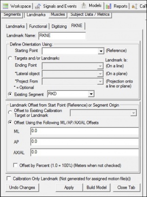
- 2. In the RKD tab, enter these values:
|
- 5. Click on Build Model.
- 6. Click on Close Tab before proceeding.

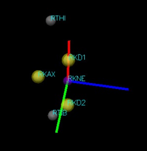
The resulting segment coordinate system is displayed. The z-axis (blue line) of the KAD segment coordinate system is parallel to the KAD axis.

Step 3: Create a landmark at the origin of the KAD.
This step creates a landmark at the origin of the KAD. The landmark is assumed to be placed identically with the lateral knee marker in the movement trials. If the Right Lateral Knee marker is labeled RKNE, then the landmark should be labeled RKNE as well. This landmark is only created so the RKNE may be selected from the list of tracking targets for the thigh. When the RKNE target exists in the dynamic trial, it will instead be used to track the segment.
1. Create RKNE:
- Click Landmarks button
- Click Add New Landmark button
- Create Landmark: RKNE
Landmark Name: RKNE
Click Existing Segment: RKD
- Offset Using the Following ML/AP/AXIAL Offsets:
X: 0.0 Y: 0.0 Z: 0.0
- Do NOT Check: Offset by Percent (1.0 = 100%) (Meters when not checked)
- Do NOT Check: Calibration Only Landmark (Not generated for assigned motion file(s))
 The resulting landmark should appear at the origin of the KAD in the 3D viewer.
Step 4: Create a landmark at the Knee Joint Center
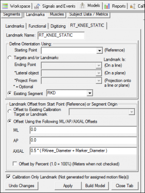
This step will create a landmark at the Knee Joint Center. It is important that the RKnee_Diameter and Marker_Radius parameters be defined previously. Next, we create a landmark for the Right Knee, RT_KNEE_STATIC.
1. Create RT_KNEE_STATIC:
- Click Landmarks button
- Click Add New Landmark button
- Create Landmark: RT_KNEE_STATIC
Landmark Name: RT_KNEE_STATIC
Click Existing Segment: RKD
- Offset Using the Following ML/AP/AXIAL Offsets:
X: 0.0 Y: 0.0 Z: 0.5 * ( RKnee_Diameter + Marker_Diameter)
- Do NOT Check: Offset by Percent (1.0 = 100%) (Meters when not checked)
- Check: Calibration Only Landmark (Not generated for assigned motion file(s))
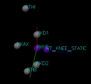
 The resulting landmark should appear in the 3D viewer.
Step 5: Create a Right Thigh Segment
1. Create the Right Hip Joint Center:
The Right Thigh segment requires the hip joint center to be created. Since the CODA pelvis automatically creates the hip joint centers, a CODA pelvis is created first to create the right hip joint center. If you already have a hip joint center created, skip this step!
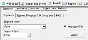
1a. Create the Pelvis:
- 1. In the Segment Name combo box select Pelvis
- 2. In the Segment Type combo box select CODA
- 3. Select the Create button
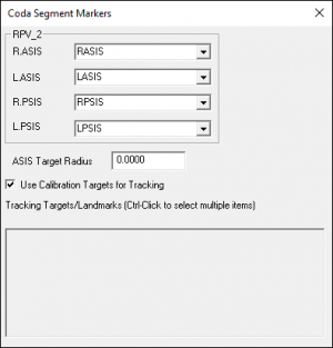
- 4. In the Pelvis dialog, enter these values:
- R.ASIS RASIS
- L.ASIS LASIS
- R.PSIS RPSIS
- L.PSIS LPSIS
- R.ASIS RASIS
- Select Tracking Targets:
- Check: Use Calibration Targets for Tracking
- Select Tracking Targets:
- 5 Click on Build Model.
- 6.Click on Close Tab before proceeding.
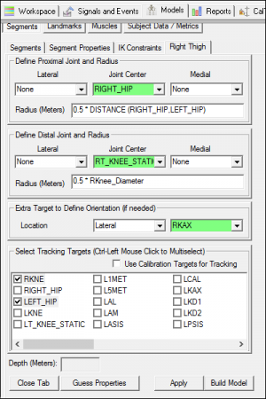
2. Create the Right Thigh:
- In Segment Name tab, select Pelvis.
- Click on the Create Segment button.
- In the Right Thigh tab, enter these values:
Define Proximal Joint and Radius
Lateral: None Joint: RIGHT_HIP Medial: None
Radius: 0.5*DISTANCE(RIGHT_HIP,LEFT_HIP)
Define Distal Joint and Radius
Lateral: None Joint: RT_KNEE_STATIC Medial: None
Radius: 0.5*RKnee_Diameter
Extra Target to Define Orientation
Location: Lateral RKAX
Select Tracking Targets:
RKNE, RIGHT_HIP, RTHI
- Click on Build Model.
- Click on Close Tab before proceeding.
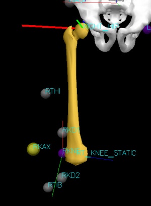
 In this implementation the frontal plane of the thigh segment is defined by the Hip Joint Center at the Knee Alignment Device. There are many other ways that the frontal plane can be defined, including specifying the THIGH marker as the lateral object.
References
- ↑ Schache, A., R. Baker, and L.W. Lamoreux. "Defining the knee joint flexion–extension axis for purposes of quantitative gait analysis: An evaluation of methods" Gait & Posture 24 (2006): 100-09


