MTD2
The Mechanical Testing Device (MTD-2) is manufactured and supported by Motion Lab Systems, Inc. The MTD-2 is a precision-machined calibration-testing tool that can be assembled in less than a minute to create a calibration-testing object suitable for a number of 3D biomechanics laboratory tests.
|
Computing the Dimensions of the CalTester Rod |
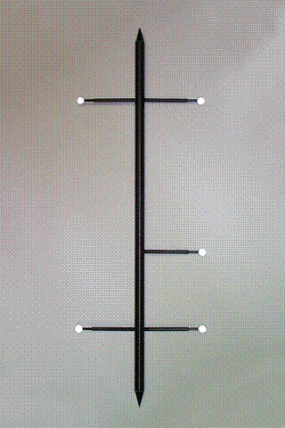
The MTD-2 is comprised of the following items supplied in a plastic storage case: Five wands with retroreflective markers. Calibration-testing rod with two conical tips Test plate and Handle, each of which has machined conical dimples into which the cone tips of the rod are placed.
All items, except the calibration-testing rod, are mechanically compatible with the MTD-1 design from Motion Lab Systems. The MTD-2 calibration-testing rod (at 904.64mm) is shorter than the MTD-1 and does not offer alternative marker wand mounting points.
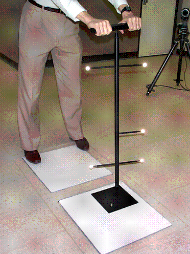
The standard configuration for use with the CalTester software uses the wands with the retroreflective marker targets attached to the calibration-testing rod in either a four or five-target configuration. It is recommended that you use the five-target configuration. The four-target arrangement is symmetrical, which can sometimes create problems when using automated labeling software.
Placement of the flat test plate
|
To use the MTD-2, place the flat test plate on the force platform that you wish to check, with the threaded screw on top so that the test plate is flush against the surface of the force platform. The test plate can be placed anywhere on the force platform, so long as the entire test plate is inside the edges of the force platform. Do not allow the test plate to overlap the force platform.
There are two conical depressions machined into the surface of the test plate. You may use either of these to apply a force to the plate during a test. Position the test plate so that the force application point is in a suitable location for your tests. Generally this will be with the test plate close to one corner of the force platform (use the force application point closer to the corner of the test plate). During a test, the tip of the calibration-testing rod can be placed in the selected force application dimple on the test plate, and a force is applied to the rod using the supplied handle. The design allows a force to be applied to the surface of the force platform without any applied moment (force couple). If the force platform surface is particularly smooth, a small piece of Dysan or other material may be placed under the test plate. This will avoid any chance of the test plate sliding, although in most cases this precaution will not be necessary. Do not attempt to use the calibration-testing rod without the test plate, as this could damage your force platform or cause the rod to slide during a test. Any sliding motion of the calibration-testing rod on the surface of the force platform would invalidate the results of the experiment. |

