PlanDSX Tutorials
| Language: | English • français • italiano • português • español |
|---|
Purpose
Overview: The purpose of this tutorial is to guide users through the process of creating a lab configuration for a trial.
Data: This tutorial requires a set of CT data. The file format for the CT data can be Dicom, Tiff, Cine or Raw files. It is also helpful to have an object file (.obj) available in order to visualize the object added at the end of the tutorial.
Steps
Visualize the lab space
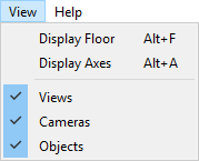
Click on the View menu and make sure that all of the View options are selected. There should be a blue box with a check mark in it next to each of the options, if PlanDSX has just been opened Display Floor and Display Axis will not be selected but Views, Cameras and Objects will be selected. Click on Display Floor and Display Axis so that they appear in the 3D-view.
Load the CT data
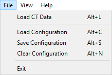
Select File→Load CT Data... or use the Alt + L shortcut. This will open a file browser window that allows you to select one of the CT data files. All of the CT data files that are in the same folder as the one that you selected will be loaded into PlanDSX, compiled into a 3D image and displayed in the center of 3D lab view.
Add X-Ray Views
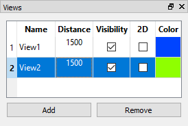
In the Views widget, click the Add button twice to add two x-ray views. The views will appear in the widget's list and in the 3D-View. To change the position of the x-ray views select the image plane and drag it to the desired position. To change the distance that the x-ray source and image plane from the center of the lab (point 0, 0, 0) double click on the distance cell in the views widget and enter the desired distance in millimetres.
Add Mocap Cameras
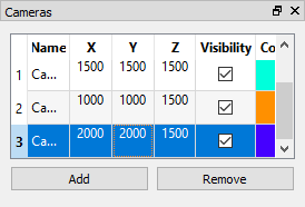
In the Mocap Cameras widget, click the Add button to create a new camera view in the widget's list and in the 3D-View. Add as many cameras as you plan to have in the lab. To change the positions of the cameras double click on the X, Y, and Z cells to enter new coordinates for the camera positions.
Add Objects
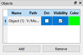
In the Objects widget, click the Add button to create a new object in the widget's list and in the 3D-view. Initially the object appears as a single dot which may not be easily visible. Double click on the cell in the Path column and a file browser will open so that you can select an object file to replace the dot which indicates the object. Once the object file is loaded the graphic can be manipulated by clicking on it and dragging it.
Save Configuration
The configuration can be saved as an .xml file by expanding the file drop down menu and clicking on the Save Configuration option, or by using the Alt + S shortcut. A file browser window will open allowing you to chose where to save the .xml file. This file can be loaded for use in the future.
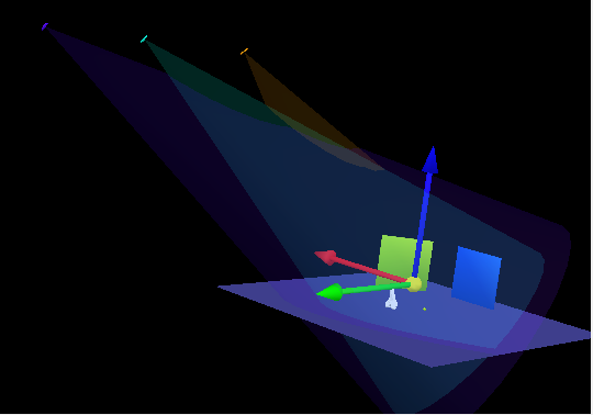
The 3D-view should look similar to the view below:
