Segment Coordinate System
An updated version of this page can be found here.
The Local or Segment Coordinate System is a right handed cartesian coordinate system the defines the position and orientation of a segment.
Specifying the Segment Coordinate System
The strategy for defining the Local Coordinate System (LCS) for a segment was derived from a strategy developed by Tom Kepple in the Physical Disabilities Branch at the National Institutes of Health and incorporated into the NIH MOVE3D software, which was the precursor to Visual3D.
6 Degree of Freedom modeling and Inverse Kinematics use the same rules for defining the segment coordinate system.
Visual3D requires that there is a static trial that is used to define a local coordinate system for each segment (Segment Coordinate System).
The original strategy assumed that the user would define 3 or 4 locations that represented the frontal plane of the segment. In the original implementation, the user had 3 options for specifying the coordinate system.
Using Markers and/or Landmarks
When we refer to locations in this document we mean either motion capture markers or landmarks (virtual markers)
We do not make a distinction on the definition of the landmark, so we could be referring to Functional Landmarks, Digitized Landmarks, relative landmarks, etc.
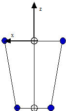
Option 1 - Specify 4 locations.
If 4 locations are specified, the frontal plane (the x-z plane by default) is computed by fitting a plane (in a least squares sense) through the four locations. The least squares fit is computed such that the sum of squares distance between the locations and the frontal plane is minimized.
Two locations must be provided at each end of the segment. It is not possible to supply 3 locations at one end and 2 locations at the other end.
The origin is located at the proximal endpoint
The axial axis (z-axis by default) passes through the segment endpoints, and is directed from the distal endpoint to the proximal endpoint.
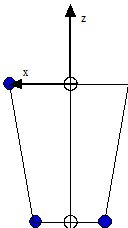
Option 2 - Specify 3 locations
Specifying 3 locations allows much more flexibility and control of the resulting segment coordinate system, but also requires additional information that is used to define the segment geometry.
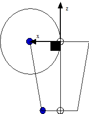
Option 3 - Specify 2 locations.
Option 4 - Visual3D Enhancements to Options 1&2.
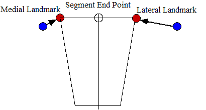
Specify 3 or 4 locations, but specifying the segment endpoint (joint center) explicitly is allowed.</xh4>
 |
This method for computing the coordinate systems are consistent with options 1 and 2, but there are now 3 possible locations to specify at each end of the segment. Any 1 or 2 locations are required, and 3 are not allowed.
Note that there are many methods of identifying a landmark at the segment endpoint; including functional methods for locating a stationary point. If a segment endpoint is used at the proximal and distal end, and only 1 location (either medial or lateral) is specified, Visual3D still requires that a distance be specified at the end defined by only 1 marker. This distance is the radius of the segment end (the other radius can be computed from the two locations), and is used to define the geometrical shape of the segment. Note: it is possible for the user to explicitly set the inertial properties of a segment, which means that this additional radius actually has no meaning. Visual3D still requires that a value (any value) be specified even though it has no meaning, and has no effect on the segment coordinate system. |
<xh4>Option 5 - Enhancements to Options 3.
Specify 2 locations. A third location defines the orientation (frontal or sagittal plane).</xh4>
Virtual Markers in MOVE3D and < Version 2 of Visual3D.
Landmarks were introduced to Visual3D after version 2. We originally used the term landmarks, so there wasn't a confusion with the term "virtual markers" from the early versions of Visual3D. We grew to like the term because the general definition of a virtual marker in Visual3D is consistent with the common use of the term landmarks for defining muscle origin or insertion. The term landmark therefore specifies anatomical landmarks, virtual markers, and any other location that is specified.
- Like Virtual Markers in early versions of Visual3D, Landmarks can be used to specify the segment coordinate system.
- Unlike Virtual markers, Landmarks can be used as tracking markers (e.g. computed locations used to track an object in a movement trial).


