Tutorial: Golem Upperbody Model Delete
| Language: | English • français • italiano • português • español |
|---|
This tutorial has been replaced (06 Jan 2016).
THE NEW TUTORIAL CAN BE FOUND HERE.
It only exists as a reference to compare changes with the new tutorial - BUT THIS PAGE WILL BE DELETED
If you notice any errors, please contact support.
Introduction
This tutorial describes the Golem (Plug-in gait) upperbody model as implemented in Vicon (via Bodybuilder/PIG) and how one might model it in Visual 3D. The Golem or Plug-in-Gait upper body model consists of 25 markers and 11 segments (Pelvis, Torso, Clavicles, Head, Upper Arms, Lower Arms, and Hands).
Marker Placement
This section describes the marker placement for the Golem/PIG upperbody model.
Head Markers
There are four markers for the head. A head band with permanently attached markers is often used.
- LFHD Left front head (Located approximately over the left temple)
- RFHD Right front head (Located approximately over the right temple)
- LBHD Left back head (Placed on the back of the head, in a horizontal plane of the front head markers)
- RBHD Right back head (Placed on the back of the head, in a horizontal plane of the front head markers)
Trunk Markers
These four markers define a plane hence their lateral positioning is most important.
- C7 Spinous process of the 7th cervical vertebrae. This is the most prominent spinal process on the back of the neck. Ask the subject to bend their head forward. Locate the C7 vertebra and then ask the subject to straighten their neck. Place the marker on this point.
- CLAV Jugular Notch where the clavicle meets the sternum. The marker should be placed on the bone and not in the jugular notch.
- T10 Spinous Process of the 10th thoracic vertebrae. This marker position is located by finding the inferior angle of the scapula. Move horizontally across to the vertebrae. This should be T7. Get the subject to slump forward and count down to T10 by feeling for the bony spines of each vertebra.
- STRN Xiphoid process of the Sternum. This marker must be placed on the bone just above the Xiphoid process. This marker can be problematic for women.
- LBAK or RBAK (Optional) Placed mid scapula, acts as an anti-symmetry marker strictly for autolabel purposes. Only LBAK or RBAK should be used, but not both.
Pelvis Markers
The Golem pelvis has two marker set variations: a three marker set and a four marker set. The three market set Pelvis is known as Helen Hayes (Davis) Pelvis and the four marker set Pelvis is known as the Coda Pelvis. The Pelvis Overview section discussed the differences between the two models.
This tutorial uses the CODA pelvis. The plane of the Coda Pelvis is visualized as a triangle or plane. In this case the plane is formed by the Right and Left Anterior Superior Iliac Spines (RASI and LASI) and the mid point of the Right and Left Posterior Superior Iliac Spines (RPSI, LPSI).
- RASI and LASI Place the centers of the markers over both Anterior Superior Iliac Spines (ASIS's)
- RPSI and LPSI Place the centers of the markers both Posterior Superior Iliac Spines (PSIS's).
Arm Markers
There are 6 bilateral markers (12 total) on the arms.
- LSHO Left shoulder marker, placed on top of the Acromio-clavicular joint.
- LUPA Left upper arm marker, placed on the upper arm between the elbow and the shoulder markers. Should be placed asymetrically with RUPA.
- LELB Left elbow (placed on lateral epicondyle approximating elbow joint axis)
Some users may use a wrist bar for the right and left wrist markers.
- LWRA Left wrist thumb side
- LWRB Left wrist pinkie side
- LFIN Left "finger". Actually placed on the dorsum of the hand just below the head of the second metacarpal
- RSHO Right shoulder marker, placed on top of the Acromio-clavicular joint.
- RUPA Right upper arm marker, placed on the upper arm between the elbow and the shoulder markers. Should be placed asymetrically with LUPA.
- RELB Right elbow (placed on lateral epicondyle approximating elbow joint axis)
Some users may use a wrist bar for the right and left wrist markers.
- RWRA Right wrist thumb side
- RWRB Right wrist pinkie side
- RFIN Right "finger". Actually placed on the dorsum of the hand just below the head of the second metacarpal
Subject measurements
There are 4 required bilateral anthroprometric measurements that need to be measured on the subject.
Shoulder Offset: This is the vertical distance from the center of the glenohumeral joint to the marker on the acromion calivicular joint (RSHO & LSHO). Some researchers have used the (anterior/posterior girth)/2 to establish a guideline for the parameter.
Elbow Width: This is the distance between the medial and lateral epicondyles of the humerus.
Wrist Width: This is the distance between the ulnar and radial styloids.
Hand Thickness: This is the distance between the dorsal and palmar surfaces of the hand.
Model Construction
In this tutorial we will go through the segments one by one. Each segment will have a Vicon model description and a Visual 3D model construction section.
Subject Measurements
In Visual 3D, we must create subject data metrics for the measured subject measurements: Shoulder offsets, elbow offsets, wrist offsets, and hand thickness.
To enter those measurements in Visual 3D, the user must create a Subject Data Metric for that measurement.
- Click on Subject Data/Metrics tab
- Click Add New Item
- Type in RShoulderOffset in Name
- Type in 0.02 in Value of Expression
- Click on OK
File:Golem subject data metric.jpg
RShoulderOffset should now appear in the list. Using the above steps, continue to enter the following subject data metrics:
- LShoulderOffset in Name and 0.02 in Value of Expression
- RElbowOffset in Name and 0.08 in Value of Expression
- LElbowOffset in Name and 0.08 in Value of Expression
- RWristOffset in Name and 0.04 in Value of Expression
- LWristOffset in Name and 0.04 in Value of Expression
- RHandOffset in Name and 0.03 in Value of Expression
- LHandOffset in Name and 0.03 in Value of Expression
- Marker_Diameter in Name and 0.02 in Value of Expression
Head
Vicon Model Description
The head origin is defined as the midpoint between the LFHD and RFHD markers (also denoted 'Front'). The midpoint between the LBHD and RBHD markers ('Back') is also calculated, along with the 'Left' and 'Right' sides of the head from the LFHD and LBHD midpoint, and the RFHD and RBHD midpoint respectively. The predominant head axis, the X axis, is defined as the forward facing direction (Front - Back). The secondary Y axis is the lateral axis from Right to Left (which is orthoganalized as usual).
For the static processing, the YXZ Euler angles representing the rotation from the head segment to the lab axes are calculated. The Y rotation is taken as the head Offset angle, and the mean of this taken across the trial. For the dynamic trial processing, the head Offset angle is applied around the Y axis of the defined head segment.
Visual 3D Model Construction
Landmarks need to be created for midpoint of the back of the head (MIDBACKHEAD), the midpoint of the front of the head (MIDFRONTHEAD), and the midpoint of the right side of the head (RIGHTMIDHEAD).
To create the midpoint of the back of the head landmark MIDBACKHEAD:
- Click on the Landmarks TAB
- Click on Add New Landmark tab
- In the Landmark Name box, enter MIDBACKHEAD
- In the Starting Point box, enter LBHD
- In the Ending Point box, enter RBHD
- From the Offset Using the Following AP/ML/Axial Offsets box, in the AXIAL enter 0.5
- Check the Offset by Percent (1.0=100%) (Meters when not checked)
- Click Apply.
To create the midpoint of the front of the head landmark MIDFRONTHEAD:
- Click on Add New Landmark tab
- In the Landmark Name box, enter MIDFRONTHEAD
- In the Starting Point box, enter LFHD
- In the Ending Point box, enter RFHD
- From the Offset Using the Following AP/ML/Axial Offsets box, in the AXIAL enter 0.5
- Check the Offset by Percent (1.0=100%) (Meters when not checked)
- Click Apply.
To create the midpoint of the right side of the head landmark MIDRIGHTHEAD:
- Click on Add New Landmark tab
- In the Landmark Name box, enter MIDFRONTHEAD
- In the Starting Point box, enter RBHD
- In the Ending Point box, enter RFHD
- From the Offset Using the Following AP/ML/Axial Offsets box, in the AXIAL enter 0.5
- Check the Offset by Percent (1.0=100%) (Meters when not checked)
- Click Apply.
We have now created all the needed landmarks for the head segment. To create the head segment in Visual 3D:
- Click on Segments tab
- From the Segment Name box, select Head.
- From the Segment Type box, select Visual 3D.
- Click Create.
A dialog will open that will allow us to define the segment. The Z axis, pointing upwards, is the predominant axis. This is defined as the direction from the midpoint of the LFHD and RFHD to the midpoint of LBHD and RBHD. The proximal and distal ends of the segment must be defined. The origin is MIDFRONTHEAD.
- In the Define Proximal Joint and Radius section, select MIDFRONTHEAD for the Joint.
- In the Proximal Radius box, enter distance(MIDFRONTHEAD,RFHD).
- In the Define Distal Joint and Radius section, select MIDBACKHEAD for the Joint.
- In the Distal Radius box, enter distance(MIDBACKHEAD,RBHD)
- In the Extra Target to Define Orientation section, select Lateral for the Location. and RIGHTMIDHEAD for the marker.
- In the Select Tracking Targets, click on LBHD, LFHD, RFHD, and RBHD
- Click on Build Model
You should now see a head segment on your standing model. If you do not see the head segment after clicking Build Model, double check the values you entered in the last step. The coordinate system needs to be rotated to reflect our convention (x - med/lat, y - ant/post, z vert). In addition, we need to rotate the head graphic to the correct orientation. To orient the coordinate system and the head skeleton graphic.
- Click on the Segment Properties TAB
- Click on Modify Segment Coordinates tab
- Select -Z in A/P & +Y in distal/proximal.
- Click on Ok
- Click on Rotate Scale/Graphic Model tab
- Rotate the scale/graphic 90 in vertical rotation and -180 in the clockwise rotation.
- Click on Ok
- Click on Apply
The head segment axes and graphic should now be correct.
File:Golemheadsegment2.jpg
Thorax
Vicon Model Description
The Z axis, pointing upwards, is the predominant axis. This is defined as the direction from the midpoint of the STRN and T10 to the midpoint of CLAV and C7. A secondary direction pointing forwards is the midpoint of C7 and T10 to the midpoint of CLAV and STRN. The thorax origin is then calculated from the CLAV marker, with an offset of half a marker diameter backwards along the X axis.
Visual 3D Model Construction
Landmarks need to be created for: midpoint of C7 and CLAV (MIDCLAVC7), midpoint of STRN and T10 (MIDSTRNT10), midpoint of MIDSTRNT10 and STRN to find the anterior axis of the torso (TORSO_X), and the Thorax joint center (THORAX_ORIGIN).
To create the midpoint of C7 and the CLAV landmark MIDCLAVC7:
- Click on the Landmarks TAB
- Click on Add New Landmark tab
- In the Landmark Name box, enter MIDCLAVC7
- In the Starting Point box, enter CLAV
- In the Ending Point box, enter C7
- From the Offset Using the Following AP/ML/Axial Offsets box, in the AXIAL enter 0.5
- Check the Offset by Percent (1.0=100%) (Meters when not checked)
- Click Apply.
To create the midpoint of STRN and the T10 landmark MIDSTRNT10:
- Click on Add New Landmark tab
- In the Landmark Name box, enter MIDSTRNT10
- In the Starting Point box, enter STRN
- In the Ending Point box, enter T10
- From the Offset Using the Following AP/ML/Axial Offsets box, in the AXIAL enter 0.5
- Check the Offset by Percent (1.0=100%) (Meters when not checked)
- Click Apply.
To create the midpoint of MIDSTRNT10 and STRN to find the anterior axis of the torso TORSO_X:
- Click on Add New Landmark tab
- In the Landmark Name box, enter TORSO_X
- In the Starting Point box, enter MIDSTRNT10
- In the Ending Point box, enter STRN
- From the Offset Using the Following AP/ML/Axial Offsets box, in the AXIAL enter 0.5
- Check the Offset by Percent (1.0=100%) (Meters when not checked)
- Click Apply.
To create the the Thorax joint center THORAX_ORIGIN:
- Click on Add New Landmark tab
- In the Landmark Name box, enter THORAX_ORIGIN
- In the Starting Point box, enter CLAV
- In the Ending Point box, enter C7
- From the Offset Using the Following AP/ML/Axial Offsets box, in the AXIAL enter -.00125
- Check the Offset by Percent (1.0=100%) (Meters when not checked)
- Click Apply.
We have now created all the needed landmarks for the Thorax/Ab segment. To create the Thorax/Ab segment in Visual 3D:
- Click on Segments tab
- From the Segment Name box, select Thorax/Ab.
- From the Segment Type box, select Visual 3D.
- Click Create.
A dialog will open that will allow us to define the segment. The Z axis, pointing upwards, is the predominant axis. This is defined as the direction from the midpoint of the STRN and T10 to the midpoint of CLAV and C7. The proximal and distal ends of the segment must be defined. The origin is the MIDCLAVC7.
- In the Define Proximal Joint and Radius section, select MIDCLAVC7 for the Joint.
- In the Proximal Radius box, enter 0.5*distance(LSHO,RSHO).
- In the Define Distal Joint and Radius section, select MIDSTRNT10 for the Joint.
- In the Distal Radius box, enter 0.5*distance(LSHO,RSHO)
- In the Extra Target to Define Orientation section, select Anterior for the Location. and TORSO_X for the marker.
- In the Select Tracking Targets, click on C7, CLAV, STRN, and T10
- In Depth, enter 0.14
- Click on Build Model
You should now see a thorax segment on your standing model. The thorax graphic is not oriented or scaled correctly. If you do not see the thorax segment after clicking Build Model, double check the values you entered in the last step. We need to rotate the thorax graphic to the correct orientation. To orient the thorax skeleton graphic.
- Click on the Segment Properties TAB
- In the model file, browse to find thoraciccerviclet12toacromium.v3g. A different thorax graphic will appear.
- Click on Rotate Scale/Graphic Model tab
- Rotate the scale/graphic 180 in horizontal rotation and 180 in the clockwise rotation.
- Click on Scale button
- Change the scale for both the width and depth to 120
- Click on Ok
- Click on Apply
Pelvis
Vicon Model Description
The pelvis in Golem can either be the Helen Hayes Pelvis (a three marker set) or the CODA Pelvis ( a four marker set). The three market set Pelvis is known as Helen Hayes (Davis) Pelvis and the four marker set Pelvis is known as the Coda Pelvis. The Pelvis Overview section discussed the differences between the two models.
Visual 3D Model Construction
This tutorial uses the CODA pelvis. To construct the CODA Pelvis, we begin by using the static standing trial.
- From the Model menu, select Create (Add Static Calibration File)
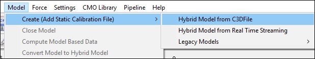
- Select Hybrid Model from C3DFile
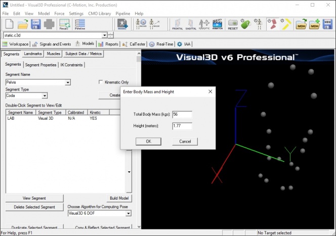
- A dialog titled Select the calibration file for the new model will appear. Select static.c3d and click Open.
- Visual3D will switch to Model Building mode automatically. The 3D viewer will display the average value of the marker locations from the standing file. The dialog bar to the left of the screen will contain a list of segments, which by default will contain only a segment representing the Laboratory.

To construct the CODA Pelvis segment:
- From the Segment Name box, select Pelvis.
- From the Segment Type box, select Coda.
- Click Create.

- A dialogue box labeled Enter Body Mass and Height will open because Visual3D needs the subject to be assigned a mass and a height. For this example, Enter 56 kg and 1.77 m, and click OK.
- A dialogue box labeled CODA Segment Markers will open. Select the markers so that they correspond to the figure below. Click Close.

- Click Build Model to build the segment. You should now see a pelvis segment on your standing model. If you do not see the pelvis segment after clicking Build Model, double check the values you entered in the last step.


Shoulder Joint Center
Vicon Model Description
The clavicles are considered to lie between the thorax origin, and the shoulder joint centers. The shoulder joint centers are defined as the origins for each clavicle. Note that the posterior part of the shoulder complex is considered too flexible to be modeled with this marker set. Initially a direction is defined, which is perpendicular to the line from the thorax origin to the SHO marker, and the thorax X axis. This is used to define a virtual shoulder 'wand' marker. The chord function is then used to define the shoulder joint centre (SJC) from the Shoulder offset, thorax Origin, SHO marker and shoulder 'wand'.
Visual 3D Model Construction
This tutorial uses the previously modeled thorax segment to define the shoulder joint center.
The right and left shoulder joint centers (RSHJC, LSHJC) landmarks are created from a plane defined by the shoulder marker, Thorax/ab segment, and the -.09*DISTANCE(LSHO,RSHO) in the Axial direction.
To create the right shoulder joint center landmark RSHJC:
- Click on the Landmarks TAB
- Click on Add New Landmark tab
- In the Landmark Name box, enter RSHJC
- In the Starting Point box, enter RSHO
- In the Existing Segment pulldown box, enter Thorax/Ab
- From the Offset Using the Following AP/ML/Axial Offsets box, in the AXIAL enter -.09*DISTANCE(LSHO,RSHO)
- Click Apply.
To create the left shoulder joint center landmark LSHJC:
- Click on Add New Landmark tab
- In the Landmark Name box, enter LSHJC
- In the Starting Point box, enter LSHO
- In the Existing Segment pulldown box, enter Thorax/Ab
- From the Offset Using the Following AP/ML/Axial Offsets box, in the AXIAL enter -.09*DISTANCE(LSHO,RSHO)
- Click Apply.
Clavicle
Vicon Model Description
The clavicle segment is defined from the direction from the joint center to the thorax origin as the Z axis, and the shoulder wand direction as the secondary axis. The X axis for each clavicle points generally forwards, and the Y axis for the left points upwards, and the right clavicle Y axis points downwards.
Visual 3D Model Construction
The clavicle is not modeled in Visual 3D since it is not used to calculate kinematics and kinetics.
Elbow and Wrist Joint Centers
For this tutorial we will be assuming that the wrist markers are located on the wrist and not on a wrist bar.
Vicon Model Description
Elbow Joint Center
A construction vector direction is defined, being perpendicular to the plane defined by the shoulder joint center, the elbow marker (LELB) and the midpoint of the two wrist markers (LWRA, LWRB).
The elbow joint center is the defined using the chord function, in the plane defined by the shoulder joint center, the elbow marker and the previously defined construction vector.
Wrist Joint Center
This description assumes that a wrist bar is used. The wrist joint center (WJC) is then calculated. In this case the chord function is not used. The wrist joint center is simply offset from the midpoint of the wrist bar markers along a line perpendicular to the line along the wrist bar, and the line joining the wrist bar midpoint to the elbow joint center.
Visual 3D Model Construction
Wrist Joint Center
We first construct landmarks for the wrist joint centers (RWJC and LWJC) so we can use these landmarks in the elbow joint center calculations. A wrist bar is not used. The markers are placed directly on the wrists. The wrist joint center is calculated as a point midway between the two wrist markers (WRA amd WRB).
To create the right wrist joint center landmark RWJC:
- Click on the Landmarks TAB
- Click on Add New Landmark tab
- In the Landmark Name box, enter RWJC
- In the Starting Point box, enter RWRA
- In the Ending Point box, enter RWRB
- From the Offset Using the Following AP/ML/Axial Offsets box, in the AXIAL enter .5
- Check the Offset by Percent (1.0=100%) (Meters when not checked)
- Click Apply.
To create the left wrist joint center landmark LWJC:
- Click on the Landmarks TAB
- Click on Add New Landmark tab
- In the Landmark Name box, enter LWJC
- In the Starting Point box, enter LWRA
- In the Ending Point box, enter LWRB
- From the Offset Using the Following AP/ML/Axial Offsets box, in the AXIAL enter .5
- Check the Offset by Percent (1.0=100%) (Meters when not checked)
- Click Apply.
Elbow Joint Center
Now that the wrist joint center landmarks are created, we can now creare the elbow joint centers. The REJC landmark is created from a plane defined by RELB, RSHJC, and RWJC and the -(RELBOWOFFSET+Marker_Diameter)/2 in the ML direction.
To create the right elbow joint center landmark REJC:
- Click on the Landmarks TAB
- Click on Add New Landmark tab
- In the Landmark Name box, enter REJC
- In the Starting Point box, enter RELB
- In the Ending Point box, enter RSHJC
- In the Lateral object box, enter RWJC
- From the Offset Using the Following AP/ML/Axial Offsets box, in the AXIAL enter -(RELBOWOFFSET+Marker_Diameter)/2
- Click Apply.
The LEJC landmark is created from a plane defined by LELB, LSHJC, and LWJC and the -(LELBOWOFFSET+Marker_Diameter)/2 in the ML direction.
To create the left elbow joint center landmark LEJC:
- Click on the Landmarks TAB
- Click on Add New Landmark tab
- In the Landmark Name box, enter LEJC
- In the Starting Point box, enter LELB
- In the Ending Point box, enter LSHJC
- In the Lateral object box, enter LWJC
- From the Offset Using the Following AP/ML/Axial Offsets box, in the AXIAL enter -(LELBOWOFFSET+Marker_Diameter)/2
- Click Apply.
Upper Arm
Vicon Model Description
The Humerus is then defined with it's origin at the EJC, a principal Z axis from EJC to SJC, and a secondary line approximating to the X axis between the EJC and the WJC.
Visual 3D Model Construction
To create the Right Upper Arm segment in Visual 3D:
- Click on Segments tab
- From the Segment Name box, enter Right Upper Arm
- From the Segment Type box, select Visual 3D.
- Click Create.
A dialog will open that will allow us to define the segment. The Z axis, pointing upwards, is the predominant axis. This is defined as the direction from REJC to RSHJC. The proximal radius is defined as RELBOWOFFSET/2 and the distal radius is RShoulderOFFSET. The anterior direction is found from the RWJC marker. Tracking markers are RELB, REJC, RSHJC, RSHO, and RUPA. The origin is REJC.
- In the Define Proximal Joint and Radius section, select REJC for the Joint.
- In the Proximal Radius box, enter RELBOWOFFSET/2.
- In the Define Distal Joint and Radius section, select RSHJC for the Joint.
- In the Distal Radius box, enter RShoulderOFFSET
- In the Extra Target to Define Orientation section, select Anterior for the Location. and RWJC for the marker.
- In the Select Tracking Targets, click on REJC, RSHJC, RSHO, RUPA, and RELB.
- Click on Build Model
Note: the above image shows RSHJC1 for the RSHJC. You should now see a right upper arm segment on your standing model. The upper arm coordinate system and graphic are not oriented correctly. If you do not see the upper arm segment after clicking Build Model, double check the values you entered in the last step. We need to rotate the coordinate system to the correct orientation. To modify the coordinate system.
- Click on the Segment Properties TAB
- Click on Modify segment coordinate system tab
- Select -X in the A/P axis and -Z in Distal to Proximal
- Click on Ok
- Click on Apply
To create the Left Upper Arm segment in Visual 3D:
- Click on Segments tab
- From the Segment Name box, enter Left Upper Arm
- From the Segment Type box, select Visual 3D.
- Click Create.
A dialog will open that will allow us to define the segment. The Z axis, pointing upwards, is the predominant axis. This is defined as the direction from LEJC to LSHJC. The proximal radius is defined as LELBOWOFFSET/2 and the distal radius is LShoulderOFFSET. The anterior direction is found from the LWJC marker. Tracking markers are LELB, LEJC, LSHJC, LSHO, and LUPA. The origin is LEJC.
To define the left Upper Arm:
- In the Define Proximal Joint and Radius section, select LEJC for the Joint.
- In the Proximal Radius box, enter LELBOWOFFSET/2.
- In the Define Distal Joint and Radius section, select LSHJC for the Joint.
- In the Distal Radius box, enter LShoulderOFFSET
- In the Extra Target to Define Orientation section, select Anterior for the Location. and LWJC for the marker.
- In the Select Tracking Targets, click on LEJC, LSHJC, LSHO, LUPA, and LELB.
- Click on Build Model
You should now see a left upper arm segment on your standing model. The upper arm coordinate system and graphic are not oriented correctly. If you do not see the upper arm segment after clicking Build Model, double check the values you entered in the last step. We need to rotate the coordinate system to the correct orientation. To modify the coordinate system.
- Click on the Segment Properties TAB
- Click on Modify segment coordinate system tab
- Select X in the A/P axis and -Z in Distal to Proximal
- Click on Ok
- Click on Apply
File:Golem upperarms.jpg Note: upper arm bone graphic is not oriented correctly
Forearm
Vicon Model Description
The forearm origin is set at the wrist joint center. The principal axis is the Z axis, from the WJC to the EJC. The secondary line approximating to the Y axis is taken as the Y axis of the upper arm segment.
Visual 3D Model Construction
To create the Right Forearm segment in Visual 3D:
- Click on Segments tab
- From the Segment Name box, enter Right Forearm
- From the Segment Type box, select Visual 3D.
- Click Create.
A dialog will open that will allow us to define the segment. The Z axis, pointing upwards, is the predominant axis. This is defined as the direction from RWJC to REJC. The proximal radius is defined as RWRISTOFFSET/2 and the distal radius is RELBOWOFFSET/2. The lateral direction is found from the RWJC marker. Tracking markers are RELB, REJC, RSHJC, RSHO, RUPA, and RWJC. The origin is RELB.
- In the Define Proximal Joint and Radius section, select RWJC for the Joint.
- In the Proximal Radius box, enter RWRISTOFFSET/2.
- In the Define Distal Joint and Radius section, select REJC for the Joint.
- In the Distal Radius box, enter RELBOWOFFSET/2
- In the Extra Target to Define Orientation section, select Lateral for the Location. and RELB for the marker.
- In the Select Tracking Targets, click on REJC, RWJC, RELB, RFRA, RWRA, and RWRB.
- Click on Build Model
To create the Left Forearm segment in Visual 3D:
- Click on Segments tab
- From the Segment Name box, enter Left Forearm
- From the Segment Type box, select Visual 3D.
- Click Create.
A dialog will open that will allow us to define the segment. The Z axis, pointing upwards, is the predominant axis. This is defined as the direction from LWJC to LEJC. The proximal radius is defined as LWRISTOFFSET/2 and the distal radius is LELBOWOFFSET/2. The lateral direction is found from the LELB marker. Tracking markers are LELB, LEJC, LWJC, LFRA, LWRA, and LWRB. The origin is LEJC.
- In the Define Proximal Joint and Radius section, select LWJC for the Joint.
- In the Proximal Radius box, enter LWRISTOFFSET/2.
- In the Define Distal Joint and Radius section, select LEJC for the Joint.
- In the Distal Radius box, enter LELBOWOFFSET/2
- In the Extra Target to Define Orientation section, select Lateral for the Location. and LELB for the marker.
- In the Select Tracking Targets, click on LEJC, LWJC, LELB, LFRA, LWRA, and LWRB.
- Click on Build Model
File:Golem forearms.jpg Note: forearm bone graphic is not oriented correctly
Hand Joint Center
Vicon Model Description
The hand is defined by first defining it's origin. The chord function is used again for this, with the WJC, FIN marker and Hand Offset. The midpoint of the wrist bar markers is used to define the plane of calculation. This description assumes the use of wrist of a bar.
Visual 3D Model Construction
The RHANDJC landmark is created from a plane defined by RWJC, RWRA, RFIN, and and the -(RHANDOFFSET+Marker_Diameter)/2 in the ML direction.
To create the right wrist joint center landmark RHANDJC:
- Click on the Landmarks TAB
- Click on Add New Landmark tab
- In the Landmark Name box, enter RHANDJC
- In the Starting Point box, enter RFIN
- In the Ending Point box, enter RWRA
- In the Lateral object box, enter RWJC
- From the Offset Using the Following AP/ML/Axial Offsets box, in the ML enter -(RHANDOFFSET+Marker_Diameter)/2
- Click Apply.
The LHANDJC landmark is created from a plane defined by LWJC, LWRA, LFIN, and and the -(LHANDOFFSET+Marker_Diameter)/2 in the ML direction.
To create the left wrist joint center landmark LHANDJC:
- Click on the Landmarks TAB
- Click on Add New Landmark tab
- In the Landmark Name box, enter LHANDJC
- In the Starting Point box, enter LFIN
- In the Ending Point box, enter LWRA
- In the Lateral object box, enter LWJC
- From the Offset Using the Following AP/ML/Axial Offsets box, in the ML enter -(LHANDOFFSET+Marker_Diameter)/2
- Click Apply.
Hand
Vicon Model Description
The principal Z axis is then taken as the line from the hand origin to the WJC, and a secondary line approximating the Y axis is defined by direction of the line joining the wrist bar markers.
Visual 3D Model Construction
To create the Right Hand segment in Visual 3D:
- Click on Segments tab
- From the Segment Name box, enter Right Hand
- From the Segment Type box, select Visual 3D.
- Click Create.
A dialog will open that will allow us to define the segment. The Z axis, pointing upwards, is the predominant axis. This is defined as the direction from RWJC to RHANDJC. The proximal radius is defined as RWRISTOFFSET/2 and the distal radius is RHANDOFFSET/2. The posterior direction is found from the RFIN marker. Tracking markers are RFIN, RWRA, and RWRB. The origin is RWJC.
- In the Define Proximal Joint and Radius section, select RWJC for the Joint.
- In the Proximal Radius box, enter RWRISTOFFSET/2.
- In the Define Distal Joint and Radius section, select RHANDJC for the Joint.
- In the Distal Radius box, enter RHANDOFFSET/2
- In the Extra Target to Define Orientation section, select Posterior for the Location. and RFIN for the marker.
- In the Select Tracking Targets, click on RFIN, RWRA, and RWRB.
- Click on Build Model
You should now see the right hand segment on your standing model. The right hand segment coordinate system and graphic are not oriented correctly. If you do not see the hand segment after clicking Build Model, double check the values you entered in the last step. We need to rotate the coordinate system to the correct orientation.
To modify the right hand segment coordinate system.
- Click on the Segment Properties TAB
- Click on Modify segment coordinate system tab
- Select -Y in the A/P axis and +Z in Distal to Proximal
- Click on Ok
- Click on Apply
To modify the right hand segment graphic.
- Click on the Segment Properties TAB
- Click on Rotate/Scale Graphic Model tab
- Select Rotate and in the Clockwise Rotation enter -90
- Select Scale and in the Scale Height enter 150,in the Scale Width enter 150, and in the Scale Depth enter 150.
- Click on Ok
- Click on Apply
To create the Left Hand segment in Visual 3D:
- Click on Segments tab
- From the Segment Name box, enter Left Hand
- From the Segment Type box, select Visual 3D.
- Click Create.
A dialog will open that will allow us to define the segment. The Z axis, pointing upwards, is the predominant axis. This is defined as the direction from LWJC to LFIN. The proximal radius is defined as LWRISTOFFSET/2 and the distal radius is RHANDOFFSET/2. The posterior direction is found from the LFIN marker. Tracking markers are LFIN, LWRA, and LWRB. The origin is LWJC.
- In the Define Proximal Joint and Radius section, select LWJC for the Joint.
- In the Proximal Radius box, enter LWRISTOFFSET/2.
- In the Define Distal Joint and Radius section, select LHANDJC for the Joint.
- In the Distal Radius box, enter RHANDOFFSET/2
- In the Extra Target to Define Orientation section, select Posterior for the Location. and LFIN for the marker.
- In the Select Tracking Targets, click on LFIN, LWRA, and LWRB.
- Click on Build Model
To modify the left hand segment coordinate system.
- Click on the Segment Properties TAB
- Click on Modify segment coordinate system tab
- Select -Y in the A/P axis and +Z in Distal to Proximal
- Click on Ok
- Click on Apply
To modify the left hand segment graphic.
- Click on the Segment Properties TAB
- Click on Rotate/Scale Graphic Model tab
- Select Rotate and in the Clockwise Rotation enter 90
- Select Scale and in the Scale Height enter 150,in the Scale Width enter 150, and in the Scale Depth enter 150.
- Click on Ok
- Click on Apply
Summary
This tutorial walked you through Visual 3D construction of the Golem upper body model. At this time, no comparisons have been made between this model and the one provided by Vicon. The tutorial was not meant to be comprehensive and variations may exist between this version of the Golem model and the Vicon Golem model.
References
- PIGModeling Vicon documentation
- Golem Bodybuilder Model Vicon documentation
- PIGManualver1 Vicon documentation