Introduction
This tutorial describes how to implement the Golem/Plug-in Gait Upper Extremity model as implemented in Vicon (via Bodybuilder/PIG) in Visual3D. The Golem or Plug-in-Gait upper body model consists 9 segments:
- Pelvis
- Thorax
- Head
- Left/Right Upper Arms
- Left/Right Forearms
- Left/Right Hands
The Pelvis definition is not described in this tutorial, but can be found in the Lower Body Tutorial.
Definition of the Clavicle segments are also described in the Vicon documentation - but they are not used for kinetics/kinematics, and can only be tracked when using Inverse Kinematics. For this reason, these segments are not included in this model, but there is more information about this in the Clavicle section of this tutorial.
To create the pelvis and all other lower extremity segments, please view the Lower Body Tutorial.
Background
The information for this tutorial was obtained from:
- Plug-In Gait Manual (version 1) [1]
- Plug-in Gait Marker Set [2]
Documentation Differences
The tutorial tries to follow Vicon's instructions as close as possible, but some modifications were required to implement the model in Visual3D. This means that results from Vicon and Visual3D may show some small differences. Some of the bigger differences are described below.
At this time, no comparisons have been made between this model and the one provided by Vicon. The tutorial was not meant to be comprehensive and variations may exist between this version of the Golem model and the Vicon Golem model.
Segment Origin
Vicon defines the origin of the segments at the distal end of the segment. By default, Visual3D defines the origin of the segments at the proximal end of the segment. This tutorial chose to define the origin at the proximal end of the segment, as this is more convenient in Visual3D, and will have no affect on the results.
Segment Orientation
This tutorial uses the Visual3D default segment orientation. The default segment orientation for Visual3D is:
- X - ML (red)
- Y - AP (green)
- Z - Axial (bue)
If you review the Vicon documenation[1], the segment orientation and colors are different from those in Visual3D. Vicon's coordinate systems are:
- Y - ML (blue)
- X - AP (green)
- Z - Axial (red)
This means if you use the Visual3D segment orientation, when calculating joint angles, you will select an XYZ rotation sequence. This will result in joint angles provide a rotation about the mediolateral, AP, and then axial axes. This is consistent with Vicon's joint angle calculations - and with the biomechanics convention.
Data Collection
Marker Set
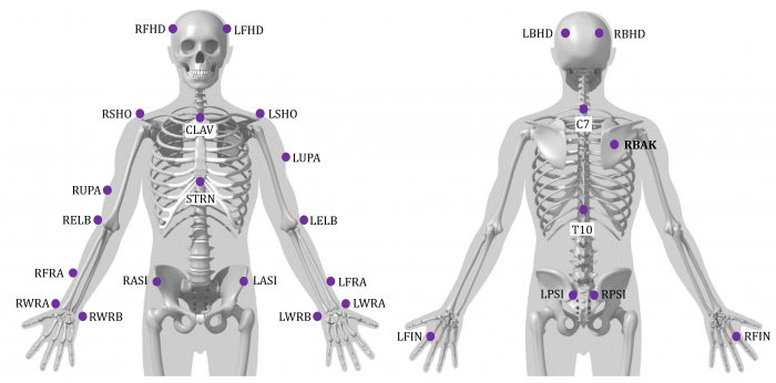
To complete this tutorial, you should use the PiG marker[2]. It will be easiest if you use the same naming convention. Please note, this is a minimal marker set, so if there is target drop out, or a target was not placed, most likely, you will not be able to use the data set. Please note this model is also very sensitive to the subject's posture during the static trial. When using this model, you should make sure that the subject is in a T-Pose during the static trial.
This image was adapted from the PiG Marker Set document [2]
Subject measurements
In addition to subject height & mass, there are 4 required bilateral anthroprometric measurements that need to be measured on the subject.
Shoulder Offset: This is the vertical distance from the center of the glenohumeral joint to the marker on the acromion calivicular joint (RSHO & LSHO). Some researchers have used the (anterior/posterior girth)/2 to establish a guideline for the parameter.
Elbow Width: This is the distance between the medial and lateral epicondyles of the humerus.
Wrist Width: This is the distance between the ulnar and radial styloids.
Hand Thickness: This is the distance between the dorsal and palmar surfaces of the hand.
Create Segments
Sample Files
Sample files can be downloaded here.
The download will contain two static trials and two CMO files:
- Sub01_Static01.c3d can be used to follow this tutorial
- Sub01_Walk01.c3d is a dynamic trial which can be associated with this static trial
- AltnerateDefinition.cmo is an example of the alternate definitions shown in the tutorial
- viconDefinition.cmo is an example of the Vicon definitions shown in the tutorial
Model Metrics
There are nine model metrics in this model which MUST be taken at the time of data collection. In some cases, Vicon requests the diameter, and in other cases, the radius is used. To "simplify" things, this tutorial will primarily the radius value.
Many of the landmarks/segment definitions are based on these metrics so it is VERY important to create these metrics.
| Model Metrics Explained
|
- Height (m): The subject's height in meters
- Mass (kg): The subject's weight in kilograms
- MarkerRadius (m): The marker radius is half the diameter of the motion capture markers used for data collection
- L/RShoulderRadius (m): The vertical offset from the base of the acromion marker to shoulder joint center[1] (pg. 18).
- L/RElbowRadius (m): Half the width of the elbow along flexion axis (roughly between the distal epicondyles of the humerus)[1] (pg. 18).
- L/RWristRadius (m): Half the mediolateral thickness of the wrist at the position where the wrist marker bar is attached[1] (pg. 18). NOTE: The Vicon documentation states the A/P thickness, but the WRA/WRB targets should be placed on the thumb/pinkie side of the wrist[2] (pg. 2), which actually defines the mediolateral border of the wrist.
- L/RHandOffset (m): The distance between the dorsum and palmar surfaces of the hand
|
| Create Model Metrics
|
|
1. Create Subject Metrics:
- Click Subject Data/Metrics button
- Select the Mass and click the Modify Selected Item button
|
Name: Mass
Value or Expression: 75
NOTE: This value MUST be changed for each subject
|
|
- Select the Height and click the Modify Selected Item button
|
Name: Height
Value or Expression: 1.8
- NOTE: This value MUST be changed for each subject
|
|
- Click Add New Item button
|
Name: MarkerRadius
Value or Expression: 0.005
- NOTE: This value MUST reflect the size of the markers used in YOUR lab
|
|
|
Name: LShoulderRadius
Value or Expression: ( 0.17*Distance(LSHO,RSHO) ) - MarkerRadius
Create the RShoulderRadius
- NOTE: The equation above is used instead of manually entering the manual measurements. This equation is from the RAB Model. Vicon's model requires the user manually collect these measurements. If using an explicit value, you MUST change this for each subject.
|
|
|
Name: LElbowRadius
Value or Expression: 0.06
Create the RElbowRadius
- NOTE: This value MUST be changed for each subject
|
|
|
Name: LWristRadius
Value or Expression: ( 0.5*DISTANCE(LWRA,LWRB) ) - MarkerRadius
Create the RWristRadius
- NOTE: The above equation only works if the mediolateral wrist targets are placed directly on the wrist. If the wrist targets are placed on a wand, you will need to explicitly specify the wrist radius. If using an explicit value, you MUST change this for each subject.
|
|
|
Name: LHandOffset
Value or Expression: 0.03
Create the RHandOffset
- NOTE: This value MUST be changed for each subject
|
|
|
|
Head Segment
Prior to creating the head segment, 3 landmarks must be created:
- Head_Front - the midpoint between the LBHD and RBHD
- Head_Back - the midpoint between the LBHD and RBHD
- Head_Right - the midpoint between the RFHD and RBHD
The origin is then defined at the Head_Front landmark. The AP axis is along the line from the Head_Front to Head_Back landmarks. The ML axis is defined using the Head_Right landmark. [1] pg.41
NOTE: The Head_Mid landmark is used as the distal end of the segment so that the segment geometry is created in the appropriate location.
| Head Landmarks
|
|
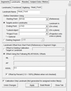
1. Create Head_Front:
- Click Landmarks button
- Click Add New Landmark button
- Create Landmark: Head_Front
|
Landmark Name: Head_Front
Define Orientation Using:
Starting Point: RFHD
Ending Point: LFHD
|
|
- Offset Using the Following ML/AP/AXIAL Offsets:
AXIAL: 0.5
- Check: Offset by Percent (1.0 = 100%)
- Check: Calibration Only Landmark
|
|
|
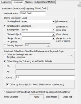
2. Create Head_Back:
- Click Landmarks button
- Click Add New Landmark button
- Create Landmark: Head_Back
|
Landmark Name: Head_Back
Define Orientation Using:
Starting Point: RBHD
Ending Point: LBHD
|
|
- Offset Using the Following ML/AP/AXIAL Offsets:
AXIAL: 0.5
- Check: Offset by Percent (1.0 = 100%)
- Check: Calibration Only Landmark
|
|
|
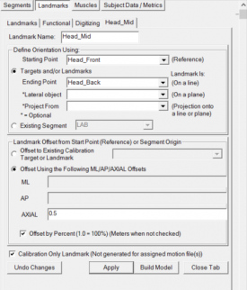
3. Create Head_Mid:
- Click Landmarks button
- Click Add New Landmark button
- Create Landmark: Head_Mid
|
Landmark Name: Head_Mid
Define Orientation Using:
Starting Point: Head_Front
Ending Point: Head_Back
|
|
- Offset Using the Following ML/AP/AXIAL Offsets:
AXIAL: 0.5
- Check: Offset by Percent (1.0 = 100%)
- Check: Calibration Only Landmark
|
|
|
4. Create Head_Right:
- Click Landmarks button
- Click Add New Landmark button
- Create Landmark: Head_Right
|
Landmark Name: Head_Right
Define Orientation Using:
Starting Point: RFHD
Ending Point: RBHD
|
|
- Offset Using the Following ML/AP/AXIAL Offsets:
AXIAL: 0.5
- Check: Offset by Percent (1.0 = 100%)
- Check: Calibration Only Landmark
|

|
|
| Head Definition
|
|
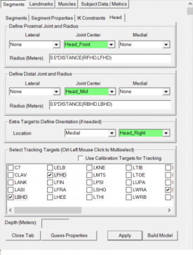
1. Create Head Segment:
- In the Segments tab, select Head in the Segment Name box.
- Click on the Create Segment button.
- In the Head tab, enter these values:
|
Define Proximal Joint and Radius
Lateral: None Joint: Head_Front Medial: None
Radius: 0.5*DISTANCE(RFHD,LFHD)
Define Distal Joint and Radius
Lateral: None Joint: Head_Mid Medial: None
Radius: 0.5*DISTANCE(RBHD,LBHD)
Extra Target to Define Orientation
Location: Medial Head_Right
Select Tracking Targets:
LBHD, LFHD, RBHD, RFHD
|
|
- Click on Build Model.
- Click on Close Tab before proceeding.
|
|
|
3. Change the graphic:
- Model File: head_c7_top.v3g
4. Rotate/Scale the Graphic Model:
- Rotate:
|
Vertical Rotation: 90
Horizontal Rotation: 0
Clockwise Rotation: 180
|
|
- Move:
|
Move Left/Right: 0
Move Back/Forward: 55
Move Up/Down: 40
|
|
- Scale:
|
Scale Height: 200
Scale Width: 200
Scale Depth: 200
|
|
|
|
|
Trunk
Prior to creating the trunk segment, 3 landmarks must be created:
- Thorax_Prox - the midpoint between the CLAV and C7
- Thorax_Dist - the midpoint between the STRN and T10
- Thorax_AP - the midpoint between the CLAV and STRN
The origin is defined at the Thorax_Prox landmark (see NOTE below). The Axial (Z) axis is defined along the line from the Thorax_Prox to Thorax_Dist. The AP axis is defined by the Thorax_AP landmark.
NOTE: If you read the Vicon documentation, you will notice that the origin is located by the CLAV marker. In Visual3D, the segment geometry is defined along the long axis (in this case, the Z axis) - the long axis is defined along the line from the proximal to distal end. If the origin (proximal end) was defined at the CLAV marker, the center of mass for the trunk would be created anterior to the actual center of mass. For this reason, in the Visual3D representation, the origin is defined at the mid point between the CLAV and C7 targets. The orientation of the coordinate system is still defined the same, so the joint angles will not be affected by this change.
| Trunk Landmarks
|
|
1. Create Thorax_Prox:
- Click Landmarks button
- Click Add New Landmark button
- Create Landmark: Thorax_Prox
|
Landmark Name: Thorax_Prox
Define Orientation Using:
Starting Point: CLAV
Ending Point: C7
|
|
- Offset Using the Following ML/AP/AXIAL Offsets:
AXIAL: 0.5
- Check: Offset by Percent (1.0 = 100%)
- Check: Calibration Only Landmark
|

|
|
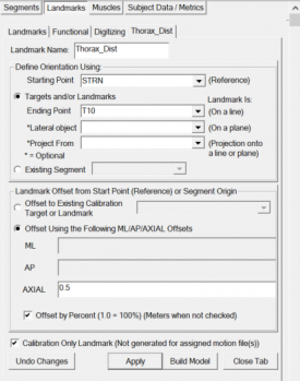
2. Create Thorax_Dist:
- Click Landmarks button
- Click Add New Landmark button
- Create Landmark: Thorax_Dist
|
Landmark Name: Thorax_Dist
Define Orientation Using:
Starting Point: STRN
Ending Point: T10
|
|
- Offset Using the Following ML/AP/AXIAL Offsets:
AXIAL: 0.5
- Check: Offset by Percent (1.0 = 100%)
- Check: Calibration Only Landmark
|
|
|
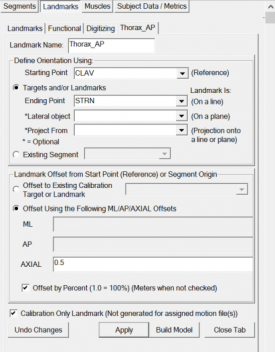
3. Create Thorax_AP:
- Click Landmarks button
- Click Add New Landmark button
- Create Landmark: Thorax_AP
|
Landmark Name: Thorax_AP
Define Orientation Using:
Starting Point: CLAV
Ending Point: STRN
|
|
- Offset Using the Following ML/AP/AXIAL Offsets:
AXIAL: 0.5
- Check: Offset by Percent (1.0 = 100%)
- Check: Calibration Only Landmark
|
|
|
| Trunk Definition
|
|
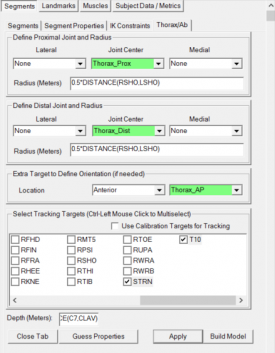
1. Create Thorax/Ab Segment:
- In the Segments tab, select Thorax/Ab in the Segment Name box.
- Click on the Create Segment button.
- In the Thorax/Ab tab, enter these values:
|
Define Proximal Joint and Radius
Lateral: None Joint: Thorax_Prox Medial: None
Radius: 0.5*DISTANCE(RSHO,LSHO)
Define Distal Joint and Radius
Lateral: None Joint: Thorax_Dist Medial: None
Radius: 0.5*DISTANCE(RSHO,LSHO)
Extra Target to Define Orientation
Location: Anterior Thorax_AP
Select Tracking Targets:
C7, CLAV, STRN, T10
Depth (Meters):
0.5*DISTANCE(C7,CLAV)
|
|
- Click on Build Model.
- Click on Close Tab before proceeding.
|
|
|
Clavicle
The clavicle is used as an intermediate segment in Vicon, and is not used for kinematics or kinetics, so there is no reason to create the clavicle in Visual3D when reproducing the Plug in Gait model.
However, if you still wish to create the Clavicle, instructions can be found here. If you are tracking using 6 DOF (the default), do NOT create the Clavicle, however if you are using Inverse Kinematics, it is ok to create the Clavicle.
Upper Arm
Prior to creating the upper arm segment, 3 landmarks must be created:
- L/RSJC - The shoulder joint center; there are two ways to define this (explained later)
- L/RWJC - The wrist joint center; the midpoint between the L/RWRA and L/RWRB targets (the mediolateral wrist targets)
- L/REJC - The elbow joint center; the L/RELB (lateral elbow target) target is created perpendicular to the plane defined by the SJC, WJC, and ELB. It is offset by the elbow radius measurement.
Upper Arm Landmarks
These landmarks are required to create the Upper Arm segment, regardless if you use the Alternative Shoulder Definition (described above) or the Vicon Shoulder Definition.
In the instructions below, the definition of the shoulder joint center (SJC) is different from Vicon's shoulder definition. In the definition below, the SJC is created below the SHO target in the -Z direction of the trunk coordinate system. I recommend using this SJC definition since it is more straight forward (more intuitive) and leaves less room for error. If you would like to use the Vicon Definition for the shoulder joint center, you should follow the instructions for the Clavicle Landmarks. Regardless of whether you use the SJC method below, or the Vicon definition, you can use either the Vicon or Alternative definition for the Upper Arm Segment.
| Upper Arm Landmarks
|
|
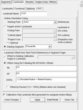
1. Create LSJC:
- Click Landmarks button
- Click Add New Landmark button
- Create Landmark: LSJC
|
Landmark Name: LSJC
Define Orientation Using:
Starting Point: LSHO
Existing Segment: Thorax/Ab
|
|
- Offset Using the Following ML/AP/AXIAL Offsets:
ML: 0.0
AP: 0.0
AXIAL: - ( LShoulderRadius + MarkerRadius )
- Do NOT Check: Offset by Percent (1.0 = 100%)
- Check: Calibration Only Landmark
2. Create RSJC:
- When defining the right landmark, use same definitions as for the left landmark
|
|
|
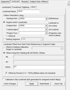
3. Create LWJC:
- Click Landmarks button
- Click Add New Landmark button
- Create Landmark: LWJC
|
Landmark Name: LWJC
Define Orientation Using:
Starting Point: LWRA
Ending Point: LWRB
|
|
- Offset Using the Following ML/AP/AXIAL Offsets:
AXIAL: 0.5
- Check: Offset by Percent (1.0 = 100%)
- Do NOT Check: Calibration Only Landmark
|
|
4. Create RWJC:
- When defining the right landmark, use same definitions as for the left landmark
|
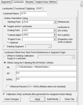
5. Create LEJC:
- Click Landmarks button
- Click Add New Landmark button
- Create Landmark: LEJC
|
Landmark Name: LEJC
Define Orientation Using:
Starting Point: LELB
Ending Point: LSJC
Lateral Object: LWJC
|
|
- Offset Using the Following ML/AP/AXIAL Offsets:
ML: - ( LElbowRadius + MarkerRadius )
AP: 0.0
AXIAL: 0.0
- Do NOT Check: Offset by Percent (1.0 = 100%)
- Check: Calibration Only Landmark
|
|
6. Create REJC:
- When defining the right landmark, use same definitions as for the left landmark
|
Upper Arm Alternate Definition
The origin is defined at the SJC. The Axial axis is defined along the line from the SJC to EJC. The ML axis is along the line from the EJC to the ELB.
| Upper Arm - Alternate Definition
|
|
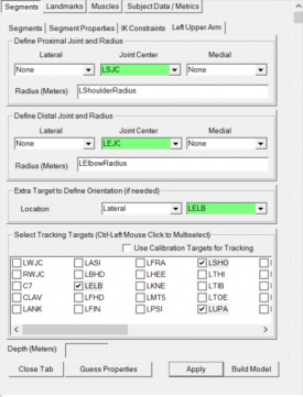
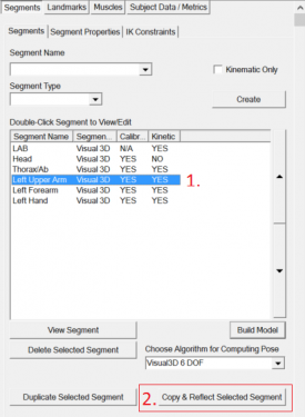
1. Create Left Upper Arm Segment:
- In the Segments tab, select Left Upper Arm in the Segment Name box.
- Click on the Create Segment button.
- In the Left Upper Arm tab, enter these values:
|
Define Proximal Joint and Radius
Lateral: None Joint: LSJC Medial: None
Radius: LShoulderRadius
Define Distal Joint and Radius
Lateral: None Joint: LEJC Medial: None
Radius: LElbowRadius
Extra Target to Define Orientation
Location: Lateral LELB
Select Tracking Targets:
LELB, LSHO, LUPA
|
|
- Click on Build Model.
- Click on Close Tab before proceeding.
|
|
|
2. Create Right Upper Arm Segment:
- In the Segments tab, click the Left Upper Arm in the created segment list.
- Click the Copy & Reflect Selected Segment button.
- In the Right Upper Arm tab, make sure the right side values are displayed (the radius values are often not updated correctly - so make sure to update these for the right side).
|
|
|
Upper Arm Vicon Definition
The origin is defined at the SJC. The Axial axis is defined along the line from the SJC to EJC. The ML axis is perpendicular to the plane defined by the SJC, EJC, and WJC.
NOTE: Since the SJC, EJC, and WJC landmarks are nearly colinear, creating the ML axis perpendicular to this plane can cause inconsistencies. For example, if you download the PiG_UE_Vicon.cmo file, you will notice the ML axis for the upper arm is pointing up. If you change the LElbowRadius to 0.05 (from 0.06), and hit Recalc, the ML axis will rotate 180 degrees. This seems to leave a lot to chance... You will also notice that the ML axis is not aligned with the ELB target. Typically, the flexion/extension axis is aligned with line between the elbow joint center and lateral epicondyle. For these reasons, I would recommend using the Alternative Definition for the Upper Arm.
| Upper Arm - Vicon Definition
|
|
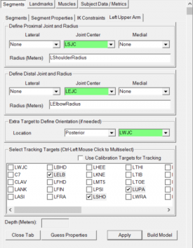
1. Create Left Upper Arm Segment:
- In the Segments tab, select Left Upper Arm in the Segment Name box.
- Click on the Create Segment button.
- In the Left Upper Arm tab, enter these values:
|
Define Proximal Joint and Radius
Lateral: None Joint: LSJC Medial: None
Radius: LShoulderRadius
Define Distal Joint and Radius
Lateral: None Joint: LEJC Medial: None
Radius: LElbowRadius
Extra Target to Define Orientation
Location: Posterior LWJC
Select Tracking Targets:
LELB, LSHO, LUPA
|
|
- Click on Build Model.
- Click on Close Tab before proceeding.
|
|
|
2. Create Right Upper Arm Segment:
- In the Segments tab, click the Left Upper Arm in the created segment list.
- Click the Copy & Reflect Selected Segment button.
- In the Right Upper Arm tab, make sure the right side values are displayed (the radius values are often not updated correctly - so make sure to update these for the right side).
|
|
|
Forearm
Two options to define the forearm are provided. One follows the Vicon Definition, and the other is an Alternate Definition, which is more consistent with biomechanics standards.
Alternate Forearm Definition
The origin is defined at the elbow joint center. The Axial axis (Z) is defined along the line between the elbow joint center to the wrist joint center, and the mediolateral axis is aligned with that of the mediolateral wrist targets.
Since supination/pronation actually occurs by rotating the forearm, this motion should appear in the elbow joint angle. The alternate definition defines the forearm so that supination/pronation occurs at the elbow joint.
Another difference between the Vicon definition and the alternate definition is that the ELB target is placed on the humerus, so it shouldn't really be used to track the forearm. For this reason, in the alternate definition, a landmark at the distal end of the upper arm is used to track the forearm.
| Forearm Landmarks - Alternate Definition
|
|
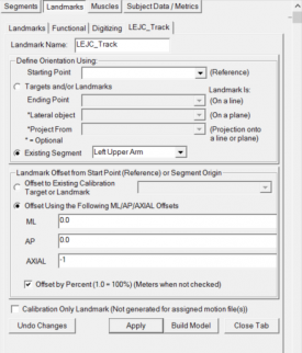
1. Create LEJC_Track:
- Click Landmarks button
- Click Add New Landmark button
- Create Landmark: LEJC_Track
|
Landmark Name: LEJC_Track
Define Orientation Using:
Existing Segment: Left Upper Arm
|
|
- Offset Using the Following ML/AP/AXIAL Offsets:
ML: 0.0
AP: 0.0
AXIAL: -1
- Check: Offset by Percent (1.0 = 100%)
- Do NOT Check: Calibration Only Landmark
|
|
2. Create REJC_Offset:
- When defining the right landmark, use same definitions as for the left landmark
|
| Forearm - Alternate Definition
|
|
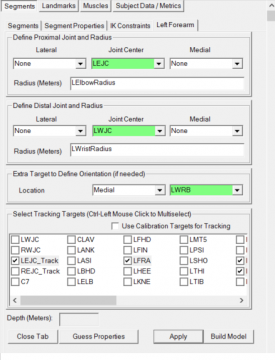
1. Create Left Forearm Segment:
- In the Segments tab, select Left Forearm in the Segment Name box.
- Click on the Create Segment button.
- In the Left Forearm tab, enter these values:
|
Define Proximal Joint and Radius
Lateral: None Joint: LEJC Medial: None
Radius: LElbowRadius
Define Distal Joint and Radius
Lateral: None Joint: LWJC Medial: None
Radius: LWristRadius
Extra Target to Define Orientation
Location: Medial LWRB
Select Tracking Targets:
LEJC_Track, LFRA, LWRA, LWRB
|
|
- Click on Build Model.
- Click on Close Tab before proceeding.
|
|
The image to the right (and all other images in this tutorial) show a mediolateral view of the segment coordinate system after it has been modified.
|
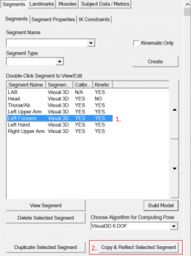
2. Create Right Forearm Segment:
- In the Segments tab, click the Left Forearm in the created segment list.
- Click the Copy & Reflect Selected Segment button.
- In the Right Forearm tab, make sure the right side values are displayed (the radius values are often not updated correctly - so make sure to update these for the right side).
|
|
|
Vicon Forearm Definition
In the Vicon Definition, the Radius segment or Forearm segment is modeled as a hinge joint (see NOTE below).
The origin is defined at the elbow joint center. The Axial axis (Z) is defined along the line between the elbow joint center to the wrist joint center, and the mediolateral axis is aligned with that of the upper arm.[1] pg. 46
NOTE: Since supination/pronation occurs by rotating the forearm, this definition is atypical and is specific to the Plug-in Gait Model. The Plug-in Gait model is created so that supination/pronation will be seen in the wrist joint angle instead of the elbow joint angle.
| Forearm Landmarks - Vicon Definition
|
|
1. Create LFA_Offset:
- Click Landmarks button
- Click Add New Landmark button
- Create Landmark: LFA_Offset
|
Landmark Name: LFA_Offset
Define Orientation Using:
Starting Point: LEJC
Existing Segment: Left Upper Arm
|
|
- Offset Using the Following ML/AP/AXIAL Offsets:
ML: 0.05
AP: 0.0
AXIAL: 0.0
- Do NOT Check: Offset by Percent (1.0 = 100%)
- Check: Calibration Only Landmark
|
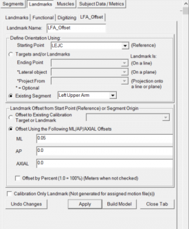
|
2. Create REJC_Offset:
- When defining the right landmark, use same definitions as for the left landmark, EXCEPT :
- Specify the ML: offset as -0.05
|
| Forearm - Vicon Definition
|
|
1. Create Left Forearm Segment:
- In the Segments tab, select Left Forearm in the Segment Name box.
- Click on the Create Segment button.
- In the Left Forearm tab, enter these values:
|
Define Proximal Joint and Radius
Lateral: None Joint: LEJC Medial: None
Radius: LElbowRadius
Define Distal Joint and Radius
Lateral: None Joint: LWJC Medial: None
Radius: LWristRadius
Extra Target to Define Orientation
Location: Medial LFA_Offset
Select Tracking Targets:
LWJC, LELB, LFRA
|
|
- Click on Build Model.
- Click on Close Tab before proceeding.
|
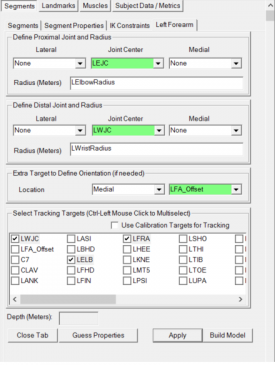
|
The image to the right (and all other images in this tutorial) show a mediolateral view of the segment coordinate system after it has been modified.
|
2. Create Right Forearm Segment:
- In the Segments tab, click the Left Forearm in the created segment list.
- Click the Copy & Reflect Selected Segment button.
- In the Right Forearm tab, make sure the right side values are displayed (the radius values are often not updated correctly - so make sure to update these for the right side).
|
|
|
Hand
The origin of the hand is at the midpoint between the wrist targets. The Axial (Z) axis is along the line from the wrist joint center to the hand joint center. The flexion/extension axis is defined along the line between the mediolateral wrist targets. [1] pg. 47
The definition of the hand joint center is not described as clearly as other joint centers... in this interpretation, the hand joint center is offset medially from the FIN target (which is on the dorsum of the hand at the head of the second metacarpal [2] pg. 3). This places the hand joint center closer to the middle of the hand (ex. by the third metacarpal).
| Hand Landmarks
|
|
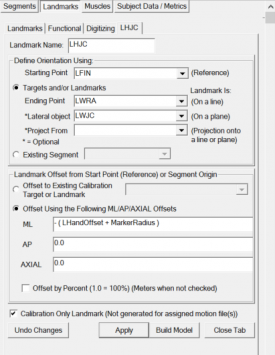
1. Create LHJC:
- Click Landmarks button
- Click Add New Landmark button
- Create Landmark: LHJC
|
Landmark Name: LHJC
Define Orientation Using:
Starting Point: LFIN
Ending Point: LWRA
Lateral Object: LWJC
|
|
- Offset Using the Following ML/AP/AXIAL Offsets:
ML: - ( LHandOffset + MarkerRadius )
AP: 0.0
AXIAL: 0.0
- Do NOT Check: Offset by Percent (1.0 = 100%)
- Check: Calibration Only Landmark
|
|
2. Create RHJC:
- When defining the right landmark, use same definitions as for the left landmark
|
| Hand Definition
|
|
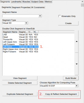
1. Create Left Hand Segment:
- In the Segments tab, select Left Hand in the Segment Name box.
- Click on the Create Segment button.
- In the Left Hand tab, enter these values:
|
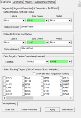
Define Proximal Joint and Radius
Lateral: None Joint: LWJC Medial: None
Radius: LWristRadius
Define Distal Joint and Radius
Lateral: None Joint: LHJC Medial: None
Radius: LHandOffset
Extra Target to Define Orientation
Location: Medial LWRB
Select Tracking Targets:
LFIN, LWRA, LWRB
|
|
- Click on Build Model.
- Click on Close Tab before proceeding.
|
|
The image to the right (and all other images in this tutorial) show a mediolateral view of the segment coordinate system after it has been modified.
|
2. Create Right Hand Segment:
- In the Segments tab, click the Left Hand in the created segment list.
- Click the Copy & Reflect Selected Segment button.
- In the Right Hand tab, make sure the right side values are displayed (the radius values are often not updated correctly - so make sure to update these for the right side).
|
|
|
References


