Tutorial: Plug-In Gait Lower-Limb
| Language: | English • français • italiano • português • español |
|---|
N.B. While every effort has been made to ensure the correct implementation of the Plug-In Gait model in Visual3D, some differences may still persist, most likely caused by the different pose estimations used within Nexus and Visual3D. Please report any errors to support@c-motion.com.
NOTE: This tutorial has been updated. The original format can be found here.
Introduction
The conventional gait model (CGM) has many variations and can go by many names: Helen Hayes, Vicon Clinical Manager, Newington, and Cleveland Clinic to name a few. We highly recommend reading the Tutorial: Building a Conventional Gait Model prior to going through this tutorial.
Workstation or Nexus users will be familiar with the Plug-In Gait variation as Vicon's implementation of the CGM.
In this tutorial, we describe this implementation of Vicon's Plug-In Gait using Visual3D.
Pose Estimation
Plug-In Gait uses a Direct (Non-Optimal) Pose Estimation for computing the position and orientation of each segment based on a set of 3 tracking markers.
Visual3D uses either Segment Optimization or Global Optimization pose estimation algorithms.
The results of the implementation of the Plug-In Gait model in Visual3D will differ slightly from the Vicon PIG implementation, but the differences are sufficiently modest that there are no clinically significant differences.
Conventional Gait Model Decisions
Since there are variations of the conventional gait model, decisions must be made prior to marker placement and data collection. The diagram below lays out some of the decisions based on body segment. This is not comprehensive since many variations exist. The following sections describe the conventional gait model marker placement locations and challenges based on these options.
File:Conventional gait model decisions1.png
In the case of the Plug-In Gait, the decisions have already been made for option 2(c), 4(b) and 5(b). Using Visual3D, it is possible to opt for different model decisions if needed or relevant. This would however not be consistent with the Plug-In Gait's implementation per se.
Manual Metrics For Plug-In Gait
The following should be measured during the data collection:
- Height (m)
- Weight (kg)
- Left and Right Knee width (m)
- Left and Right Ankle width (m)
- Marker Radius (m)
The following metrics can be collected manually, or estimated using equations (if estimated using equations, they do not need to be manually recorded):
- Left and Right Leg length (m)
- This can be estimated by calculating the distance from the ASIS target to the lateral ankle target
- ASIS to greater trochanter distance (m)
- This can be calculated from a regression equation: 0.1288*Leg Length-0.04856
NOTE: Plug-in Gait uses the average of the two values (left and right sides) to compute the joint centers.
Plug-In Gait Marker Sets
You can place four targets on the pelvis (right/left anterior iliac spine, and right/left posterior iliac spine), or place three targets on the pelvis (right/left anterior iliac spine, and the mid point of the right/left posterior iliac spine). The images below display the four marker version of the pelvis.
The typical Plug-In Gait marker set is displayed below:

Some labs use a Knee Alignment device during the static trial, and then place the lateral knee target for the dynamic trials. The image below displays the marker set for the static trial when using the knee alignment device:

| Pelvis Marker Placement Considerations |
|---|
|
The plane of the Pelvis is visualized as a triangle or plane that is formed by either the three markers: the Right and Left Anterior Superior Iliac Spines (RIAS and LIAS) and either a Sacrum marker (SACR marker) or the mid-point between the Posterior Superior Iliac Spines (SACR Landmark). Place the centers of the markers over both Anterior Superior Iliac Spines (ASIS's). The sacral marker (SACR) is placed over the mid-point of the Posterior Superior Illiac spines (RIPS and LIPS). The origin of the pelvis is at the mid-point of the ASIS markers and perpendicular to the line joining them regardless of the position of the PSIS markers. Since this is the case, medial/lateral position of the PSIS markers is not critical but care should be taken regarding the vertical position. |
| Thigh Marker Placement Considerations (without using Knee Alignment Device) |
|---|
|
The upper leg segment can be visualized as a triangle or plane formed by the Hip Joint Center (RIGH_HIP, LEFT_HIP), lateral thigh marker and lateral knee marker. Palpate lateral epicondyles to estimate the knee flexion/extension axis. Place a marker on the right and left Lateral Epicondyles (RKNE, LKNE) to approximate this axis. This should be done in the standing position with the subject passively flexing and extending the joint to confirm placement. You are looking for a point that is fixed in the thigh and about which the lower leg appears to rotate. Mark that location with eyeliner pencil or a pen. When not using a Knee Alignment Device (KAD) the placement of the thigh markers (RTHI, LTHI) or wands (stick on a base with an attached marker) is critical. This marker is used to define the frontal plane of the femur (knee flexion/extension axis location and orientation). The distal 1/3 of the thigh is the best location to decrease movement due to muscle bulk and swing of the hands. The vertical height is not critical but try not place the thigh marker too low on the thigh. The anterior/posterior position of this marker is critical and it is extremely difficult to visualize. Adjust the marker so that it is aligned in the plane that contains the hip and knee joint centers and the knee flexion/extension axis. Position this marker standing and observe knee flexion/extension to confirm. |
| Knee Alignment Device Placement Considerations |
|---|
|
The upper leg segment can be visualized as a triangle or plane formed by the Hip Joint Center (RIGHT_HIP, LEFT_HIP), lateral thigh marker and lateral knee marker. The difference in this variation is that a Knee Alignment Device (KAD) is used in the static trial to define the coronal plane for the knee. Palpate the lateral epicondyles to estimate the knee flexion/extension axis. Place the KAD over the epicondyles such that the device is in line with the visualized knee flexion/extension axis. This should be done in standing position. After the subject static calibration trial, remove the KAD and mark the KAD location on the lateral epicondyle with a eyeliner pencil or pen. Place a marker on that location (RKNE, LKNE). Placement of the thigh (RTHI, LTHI) markers or wands (stick on a base with an attached marker) is not critical in this case so it can be placed anywhere on the thigh. The KAD can be aligned improperly or can slip after placement. If this does occur, then the knee's frontal plane will be improperly defined. Care should be taken when using the KAD. As a safety measure, it may be best practice when using the KAD to align the thigh marker correctly or use medial knee markers (which is detailed in the next section) and collect a static trial with the KAD and one without the KAD. A choice can be made post data collection on whether to use the KAD alignment or the thigh or medial knee alignment. |
| Shank Marker Placement Considerations |
|---|
|
The lower leg segment can be visualized as a triangle or plane formed by the Knee Joint Center and the Ankle Flexion/Extension axis (Transmalleolar axis). Palpate the medial and lateral malleoli and visualize an imaginary line that runs through the transmalleolar axis. Place a marker on the right and left Lateral Malleolus (RFAL, LFAL) along that line. Remember to mark that location with eyeliner pencil or a pen. As in the thigh, the placement of the shank markers (RSK, LSK) or wands (stick on a base with an attached marker) is critical. This marker is used to define the coronal plane of the tibia (ankle flexion/extension axis location and orientation). The distal 1/3 of the tibia is the best location to decrease movement due to muscle bulk. The vertical height is not critical but try not place the shank marker too low on the shank. The anterior/posterior position of this marker is critical and it is extremely difficult to visualize. An alignment reference device such as a ruler under the subject's heel can be used to visualize the placement. Adjust the marker so that it is aligned in the plane that contains the knee and ankle joint centers and the ankle flexion/extension axis. This marker can be placed in a seated position but should be checked when standing to confirm. |
| Foot Marker Placement Considerations |
|---|
|
The foot is visualized as a line along the long axis of the foot from the 2nd metatarsal heads and the ankle joint center projected onto the plantar surface of the foot. The forefoot (toe) marker (RTOE, LTOE) is placed on the dorsal aspect on the 2nd metatarsal heads proximal to the MP joint (on the mid-foot side of the equinus break between forefoot and midfoot). Care should be taken in feet with midfoot breakdown or collapse. The placement of this marker should be proximal to the deformity to avoid exaggerating dorsiflexion in stance. The heel marker (RHEE, LHEE) is placed on the calcaneous where the medial/lateral position is in line with the ankle joint center. In a plantargrade foot, the heel marker is at the same height above the plantar surface of the foot as the toe marker. For a non-plantargrade foot as well as shoe/brace conditions, the height of the heel marker must be placed so that the line from the heel to toe (when viewed from the sagittal plane) is parallel to the plantar surface of the foot.
See Enhancing the foot segment for more detail. |
Load Static Trial
You can download the sample files here. These sample files were generously provided by Vicon (OMG plc, UK).
Load the static trial:
- From the Model menu, select Create (Add Static Calibration File)
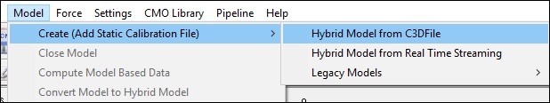
- Select Hybrid Model from C3DFile
- In the Select the calibration file for the new model dialog, select Sub01_Static_01.c3d
- If using a knee alignment device, select Sub01_Static_KAD_01.c3d
- Click Open.

Define Necessary Model Metrics
| Create Model Metrics | |||||||||||||||
|---|---|---|---|---|---|---|---|---|---|---|---|---|---|---|---|
|
Pelvis Segment
Pelvis with 4 Targets
| Pelvis Landmarks - 4 Targets | ||||
|---|---|---|---|---|
|

| Pelvis Definition - 4 Targets | ||||
|---|---|---|---|---|
|

Pelvis with 3 Targets
| Pelvis Definition - 3 Targets | ||||
|---|---|---|---|---|
|

Hip Joint Center
The CODA pelvis automatically creates hip joint centers using the Bell and Brand regression equations. The PiG model uses the Davis regression equations.
The directions below walk you through the necessary steps to create the RHJC and LHJC using the Davis regression equations. Please note, some metrics can be manually entered OR target data can be used to estimate these values.
| Create Model Metrics for Hip Joint Center | |||||||||||||||||||
|---|---|---|---|---|---|---|---|---|---|---|---|---|---|---|---|---|---|---|---|
|
| Helen Hayes Hip Landmarks | ||||||||
|---|---|---|---|---|---|---|---|---|
|
Using Knee Alignment Device (KAD)
If you are not using a Knee Alignment Device (KAD), you can skip this section.
More information about the KAD is described on the Knee Alignment Device wiki page.
| Knee Alignment Device Definition | ||||
|---|---|---|---|---|
|

| Knee Landmarks | ||||
|---|---|---|---|---|
|

Thigh Segment
| Thigh Definition | ||||
|---|---|---|---|---|
|

Shank Segment
| Shank Landmarks | ||||
|---|---|---|---|---|
|

| Shank Definition | ||||
|---|---|---|---|---|
|

Foot Segment
| Foot Landmarks | ||||
|---|---|---|---|---|
|

| Foot Definition | ||||
|---|---|---|---|---|
|

Virtual Foot Segment
| Virtual Foot Definition | ||||||||
|---|---|---|---|---|---|---|---|---|
|


References
Bell AL, Pederson DR, and Brand RA (1989) Prediction of hip joint center location from external landmarks. Human Movement Science. 8:3-16
Bell AL, Pedersen DR, Brand RA (1990) A Comparison of the Accuracy of Several hip Center Location Prediction Methods. J Biomech. 23, 617-621.
Davis RB, Ounpuu S, Tyburski D, Gage JR. (1991) "A Gait Analysis Data Collection and Reduction Technique." Human Movement Science 10: 575-587.
Kadaba MP, Ramakrishnan HK, Wootten ME (1990) "Measurement of Lower Extremity Kinematics During Level Walking." J. Orthopedic Research8: 383-392.
Serge van Sint Jan "Color Atlas of Skeletal Landmark Definitions: Guidelines for Reproducible Manual and Virtual Palpations" 2007 - Churchill Livingstone