PiG LL Original
N.B. While every effort has been made to ensure the correct implementation of the Plug-In Gait model in Visual3D, some differences may still persist, most likely caused by the different pose estimations used within Nexus and Visual3D. Please report any errors to support@c-motion.com.
Introduction
The conventional gait model (CGM) has many variations and can go by many names: Helen Hayes, Vicon Clinical Manager, Newington, and Cleveland Clinic to name a few. We highly recommend reading the Tutorial: Building a Conventional Gait Model prior to going through this tutorial.
Workstation or Nexus users will be familiar with the Plug-In Gait variation as Vicon's implementation of the CGM.
In this tutorial, we describe this implementation of Vicon's Plug-In Gait using Visual3D.
Pose Estimation
Plug-In Gait uses a Direct (Non-Optimal) Pose Estimation for computing the position and orientation of each segment based on a set of 3 tracking markers.
Visual3D uses either Segment Optimization or Global Optimization pose estimation algorithms.
The results of the implementation of the Plug-In Gait model in Visual3D will differ slightly from the Vicon PIG implementation, but the differences are sufficiently modest that there are no clinically significant differences.
Conventional Gait Model Decisions
Since there are variations of the conventional gait model, decisions must be made prior to marker placement and data collection. The diagram below lays out some of the decisions based on body segment. This is not comprehensive since many variations exist. The following sections describe the conventional gait model marker placement locations and challenges based on these options.
File:Conventional gait model decisions1.png
In the case of the Plug-In Gait, the decisions have already been made for option 2(c), 4(b) and 5(b). Using Visual3D, it is possible to opt for different model decisions if needed or relevant. This would however not be consistent with the Plug-In Gait's implementation per se.
Anthropometric measures necessary for the Conventional Gait Model
These lists describe the anthropometric measurements that are needed for the Plug-In Gait variations of the Clinical Gait Model. These are the anthropometric measurements also required in Workstation and Nexus. Some measurements are clinically measured while others are calculated from the 3D markers or a regression equation. If the no clinical measurements are entered, then calculated value is used.
The following should be measured:
While both sides should be measured independently, Plug-in Gait uses the average of the two values (left and right sides) to compute the joint centers.
- Height (Please note that contrary to Workstation and Nexus which uses mm, Visual3D uses meters as the distance unit.) (see defaults units in Visual3D)
- Weight (kg)
- Left and Right Leg length (mm) (From ASIS to medial malleolus)
- Left and Right Knee width (mm)
- Left and Right Ankle width (mm)
- Marker Radius (mm)
The following are automatically calculated in Workstation and Nexus and in Visual3D:
- Inter-ASIS distance (distance between the LASI and RASI markers)
- ASIS to greater trochanter distance (Calculated from a regression equation: 0.1288*Leg Length-0.04856)
Segment Coordinate Systems
The definitions of the segment coordinate systems are based on anatomical orientations and are consistent with many other versions of the conventional gait model.
Marker Placement
Appropriate marker placement for any model is critical. The motion system only measures the center of the marker so when placing markers on the subject, use the center of the marker as your guide and not the attached bases or wands. It is also good practice to use eyeliner pencil or pen to mark on the subject the locations of the markers. If a marker is knocked off or falls, it can easily be placed in the same location. But, one has to be very careful about replacing markers. When Segment Optimization or Global Optimization pose estimation algorithms are used, the missing marker should be replaced, then the standing trial should be collected again; simply replacing the marker is not usually sufficient.
Marker Color Convention
The different colored circles relate to the different roles of the markers.
- Red Markers are used for both the segment definition and for tracking
- Black markers are virtual markers used for both the segment definition and for tracking
Pelvis Markers
The Plug-In Gait pelvis has two marker set variations: a three-marker marker set and a four-marker marker set. In Visual3D, both marker sets can be used with the Coda Pelvis (described below). When using the four-marker marker set, Plug-In Gait computes the mid-point between LPSI and RPSI, and uses this mid-point Sacrum marker to define and track the pelvis.
For the CODA pelvis the hip joint centers are computed automatically using the Bell & Brand regression equations. However, to be consistent with Plug-In Gait, the hip joint centers must be defined using the Davis et al. regression equation.
The Pelvis Overview section and the conventional gait model discuss the differences between the two models.
Four Marker Set Pelvis

- RIAS , LIAS= Right Ilium Anterior Superior (Anterior Superior Iliac Spine)
- RIPS , LIPS= Left Ilium Posterior Superior (Posterior Superior Iliac Spine)
Three Marker Set Pelvis

- RIAS , LIAS= Right Ilium Anterior Superior (Anterior Superior Iliac Spine)
- RIPS , LIPS= Left Ilium Posterior Superior (Posterior Superior Iliac Spine)
- SACR = Sacrum (Mid-point between RIPS and LIPS)
In both cases, the plane of the Pelvis is visualized as a triangle or plane that is formed by either the three markers: the Right and Left Anterior Superior Iliac Spines (RIAS and LIAS) and either a Sacrum marker (SACR marker) or the mid-point between the Posterior Superior Iliac Spines (SACR Landmark).
Place the centers of the markers over both Anterior Superior Iliac Spines (ASIS's). The sacral marker (SACR) is placed over the mid-point of the Posterior Superior Illiac spines (RIPS and LIPS).
The origin of the pelvis is at the mid-point of the ASIS markers and perpendicular to the line joining them regardless of the position of the PSIS markers. Since this is the case, medial/lateral position of the PSIS markers is not critical but care should be taken regarding the vertical position.
Placement challenges for obese subjects
Placement on obese subjects can be challenging due to excessive tissue. Have the subject stand to palpate the ASIS's since the skin and tissue may be in different locations for the prone and standing position. There are three options for marker placement: move the ASIS markers more lateral or move the ASIS markers anterior or use the pointer to identify a virtual point.
Move ASIS markers Laterally
Move both ASIS markers lateral to the anatomical ASIS in the pelvic plane. Make sure that the lateral displacement is symmetrical between sides. Measure this distance and modify the Subject Metric Inter-ASIS_distance.
Move ASIS markers Anteriorly
Move both ASIS markers anterior (coming forward directly anterior to the landmarks so that they lie directly over them in the coronal plane of the pelvis) by an equal distance in relation to where they would have been. Measure this distance and add a landmark that specifies the actual location of the ASIS. These ASIS landmarks should be used for defining the segment coordinate system of the pelvis, but the original markers should be used as the tracking markers for the pelvis.
Use a Pointer to make ASIS Landmarks
A Digitizing Pointer can be used to identify the ASIS markers.
Upper Leg Markers

- RHJC, LHJC = Hip joint center
- RTHI, LTHI = Lateral Thigh marker
- RKNE, LKNE = Lateral Knee marker
There are two variations for the thigh segment. One in which a Knee Alignment Device (KAD) is used, one without a KAD.
Without Knee Alignment Device (KAD)
The upper leg segment can be visualized as a triangle or plane formed by the Hip Joint Center (RIGH_HIP, LEFT_HIP), lateral thigh marker and lateral knee marker. Palpate lateral epicondyles to estimate the knee flexion/extension axis. Place a marker on the right and left Lateral Epicondyles (RKNE, LKNE) to approximate this axis. This should be done in the standing position with the subject passively flexing and extending the joint to confirm placement. You are looking for a point that is fixed in the thigh and about which the lower leg appears to rotate. Mark that location with eyeliner pencil or a pen.
When not using a Knee Alignment Device (KAD) the placement of the thigh markers (RTHI, LTHI) or wands (stick on a base with an attached marker) is critical. This marker is used to define the frontal plane of the femur (knee flexion/extension axis location and orientation). The distal 1/3 of the thigh is the best location to decrease movement due to muscle bulk and swing of the hands. The vertical height is not critical but try not place the thigh marker too low on the thigh. The anterior/posterior position of this marker is critical and it is extremely difficult to visualize. Adjust the marker so that it is aligned in the plane that contains the hip and knee joint centers and the knee flexion/extension axis. Position this marker standing and observe knee flexion/extension to confirm.
Using a Knee Alignment Device (KAD)
As above, the upper leg segment can be visualized as a triangle or plane formed by the Hip Joint Center (RIGHT_HIP, LEFT_HIP), lateral thigh marker and lateral knee marker. The difference in this variation is that a Knee Alignment Device (KAD) is used in the static trial to define the coronal plane for the knee. Palpate the lateral epicondyles to estimate the knee flexion/extension axis. Place the KAD over the epicondyles such that the device is in line with the visualized knee flexion/extension axis. This should be done in standing position.
After the subject static calibration trial, remove the KAD and mark the KAD location on the lateral epicondyle with a eyeliner pencil or pen. Place a marker on that location (RKNE, LKNE). Placement of the thigh (RTHI, LTHI) markers or wands (stick on a base with an attached marker) is not critical in this case so it can be placed anywhere on the thigh.
Improper Placement of KAD
The KAD can be aligned improperly or can slip after placement. If this does occur, then the knee's frontal plane will be improperly defined. Care should be taken when using the KAD. As a safety measure, it may be best practice when using the KAD to align the thigh marker correctly or use medial knee markers (which is detailed in the next section) and collect a static trial with the KAD and one without the KAD. A choice can be made post data collection on whether to use the KAD alignment or the thigh or medial knee alignment.
Knee Width
Because no medial knee marker is used, it is critically important to measure the width of the knee (e.g. the distance between the medial and lateral epicondyles) since this information is used to identify the distal end of the thigh segment, i.e the knee joint center.
Lower Leg Markers

- RKJC, LKJC = Knee Joint Center
- RTIB, LTIB = Lateral Shank marker
- RANK, LANK = Lateral Malleolus marker
The lower leg segment can be visualized as a triangle or plane formed by the Knee Joint Center and the Ankle Flexion/Extension axis (Transmalleolar axis). Palpate the medial and lateral malleoli and visualize an imaginary line that runs through the transmalleolar axis. Place a marker on the right and left Lateral Malleolus (RFAL, LFAL) along that line. Remember to mark that location with eyeliner pencil or a pen.
As in the thigh, the placement of the shank markers (RSK, LSK) or wands (stick on a base with an attached marker) is critical. This marker is used to define the coronal plane of the tibia (ankle flexion/extension axis location and orientation). The distal 1/3 of the tibia is the best location to decrease movement due to muscle bulk. The vertical height is not critical but try not place the shank marker too low on the shank. The anterior/posterior position of this marker is critical and it is extremely difficult to visualize. An alignment reference device such as a ruler under the subject's heel can be used to visualize the placement. Adjust the marker so that it is aligned in the plane that contains the knee and ankle joint centers and the ankle flexion/extension axis. This marker can be placed in a seated position but should be checked when standing to confirm.
Ankle Diameter
Because no medial ankle marker is used, it is critically important to measure the diameter of the ankle (e.g. the distance between the medial and lateral malleolus) since this information is used to identify the distal end of the shank segment.
Foot Markers
The foot is visualized as a line along the long axis of the foot from the 2nd metatarsal heads and the ankle joint center projected onto the plantar surface of the foot.
The forefoot (toe) marker (RTOE, LTOE) is placed on the dorsal aspect on the 2nd metatarsal heads proximal to the MP joint (on the mid-foot side of the equinus break between forefoot and midfoot). Care should be taken in feet with midfoot breakdown or collapse. The placement of this marker should be proximal to the deformity to avoid exaggerating dorsiflexion in stance.
The heel marker (RHEE, LHEE) is placed on the calcaneous where the medial/lateral position is in line with the ankle joint center. In a plantargrade foot, the heel marker is at the same height above the plantar surface of the foot as the toe marker. For a non-plantargrade foot as well as shoe/brace conditions, the height of the heel marker must be placed so that the line from the heel to toe (when viewed from the sagittal plane) is parallel to the plantar surface of the foot.
- Note that inversion/eversion of the foot cannot be measured reliably with any Conventional Gait Model without any enhancement to the foot marker set
See Enhancing the foot segment for more detail.

- RAJC, LAJC = Ankle Joint Center
- RTOE, LTOE = Second metatarsal head
- RHEE, LHEE = Center of Calcaneus
Create the Lower-Limb Plug-In Gait Model
This section will detail the construction of the Plug-In Gait version of the Conventional Gait Model. Click [Plug-In Gait Lower Body Tutorial.c3d] to download the example files. These sample files were generously provided by Vicon (OMG plc, UK).
Starting with the static standing trial.
- From the Model menu, select Create (Add Static Calibration File)
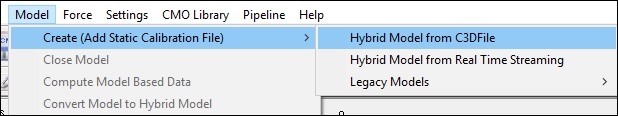
- Select Hybrid Model from C3DFile
- A dialog titled Select the calibration file for the new model will appear. Select WalkingstaticLowerBody.c3d and click Open.
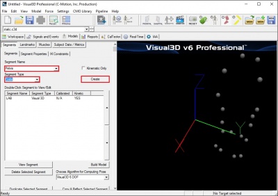
- Visual3D will switch to Model Building mode automatically. The 3D viewer will display the average value of the marker locations from the standing file. The dialog bar to the left of the screen will contain a list of segments, which by default will contain only a segment representing the Laboratory.

Pelvis
- RASI, LASI = Right Ilium Anterior Superior (Anterior Superior Iliac Spine)
- RPSI, LPSI = Left Ilium Posterior Superior (Posterior Superior Iliac Spine)
- SACR = Sacrum (Mid-point between RIPS and LIPS)
The plane of the Pelvis is visualized as a triangle or plane that is formed by the three markers: the Right and Left Anterior Superior Iliac Spines (RIAS and LIAS) and the mid-point of the Posterior Superior Iliac Spines (SACR).
Place the centers of the markers over both Anterior Superior Iliac Spines (ASIS's). The sacral marker (SACR) is placed over the mid-point of the Posterior Superior Illiac spines (RIPS and LIPS).
The origin of the pelvis is at the mid-point of the ASIS markers and perpendicular to the line joining them regardless of the position of the PSIS markers. Since this is the case, medial/lateral position of the PSIS markers is not critical but care should be taken regarding the vertical position.
Creating the SCRM landmark
If you have opted for the 4-marker pelvis marker set, where both right and left posterior superior iliac spines are identified, a sacrum landmark has to be created to define the pelvis segment.
Go to the Landmarks tab, and click on Add New Landmark:
- Landmark Name: SCRM
- Starting Point: RPSI
Targets and/or Landmark:
- Ending Point: LPSI
- Offset Using the Following ML/AP/AXIAL Offsets
- AXIAL=0.5
- Check Offset By Percent
Creating the Pelvis Segment
- From the Segment Name box, select Pelvis.
- From the Segment Type box, select Coda.
- Click Create.
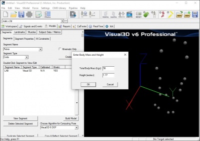
- A dialogue box labeled Enter Body Mass and Height will open because Visual3D needs the subject to be assigned a mass and a height. For this example, Enter 75 kg and 1.76 m, and click OK.
- A dialogue box labeled CODA Segment Markers will open. Select the markers so that they correspond to the figure below. Click Close.
Note: as shown in the figure above, the SCRM marker (or Landmark) is used for both R.PSIS and L.PSIS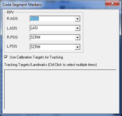 .
. - Click Build Model to build the segment. You should now see a pelvis segment on your standing model. If you do not see the pelvis segment after clicking Build Model, double check the values you entered in the last step.


Note: Creating a Coda Pelvis in Visual3D automatically generates the RIGHT_HIP and LEFT_HIP landmarks. However, these landmarks should simply be ignored since a different definition will be used to compute the hip joint centres (see section below).
Enter Subject Measurements
The Plug-In Gait conventional gait model requires measurement of leg length as well as knee and ankle width. To enter those measurements in Visual3D, a Subject Data Metric must be created for each measurement.
While these metrics are saved in the Model Template (.mdh) file, their values should be updated for each patient, to reflect patient specific measurements.

- Click on Subject Data/Metrics tab
- Click Add New Item
- Type in Left_Leg_Length in Name
- Type in 0.940 in Value of Expression
- Click on OK
- Click on Subject Data/Metrics tab
- Click Add New Item
- Type in Right_Leg_Length in Name
- Type in 0.940 in Value of Expression
- Click on OK
- Click on Subject Data/Metrics tab
- Click Add New Item
- Type in Leg_Length in Name
- Type in (Left_Leg_Length+Right_Leg_Length)/2 in Value of Expression
- Click on OK
- Click on Subject Data/Metrics tab
- Click Add New Item
- Type in Left_Knee_Width in Name
- Type in 0.105 in Value of Expression
- Click on OK
- Click on Subject Data/Metrics tab
- Click Add New Item
- Type in Right_Knee_Width in Name
- Type in 0.105 in Value of Expression
- Click on OK
- Click on Subject Data/Metrics tab
- Click Add New Item
- Type in Knee_Width in Name
- Type in (Left_Knee_Width+Right_Knee_Width)/2 in Value of Expression
- Click on OK
- Click on Subject Data/Metrics tab
- Click Add New Item
- Type in Left_Ankle_Width in Name
- Type in 0.070 in Value of Expression
- Click on OK
- Click on Subject Data/Metrics tab
- Click Add New Item
- Type in Right_Ankle_Width in Name
- Type in 0.070 in Value of Expression
- Click on OK
- Click on Subject Data/Metrics tab
- Click Add New Item
- Type in Ankle_Width in Name
- Type in (Left_Ankle_Width+Right_Ankle_Width)/2 in Value of Expression
- Click on OK
Hip Joint Center
The Hip Joint Center regression equation for the Helen Hayes (Davis) Pelvis is based on Leg Length, inter-ASIS Distance, and a regression for ASIS to Greater Trochanter distance.
- Inter ASIS distance= 3D distance between ASIS markers
- Note: that if the ASIS markers have been placed medial or lateral to the palpated landmark because the subject is obese or because the markers cannot be placed at these locations, it is important to measure the inter-ASIS distance and enter this value into the Subject Data/Metrics TAB. If this is not done, then the hip joint center calculations will be incorrect.
- Bilateral anteroposterior distance= 0.1288*Leg Length-0.04856
Estimates for the Right and Left Hip Joint Center are represented as Landmarks that are created automatically when the Helen Hayes pelvis segment is created. When using the Coda Pelvis in Visual3D, these landmarks need to be defined explicitly. The location of the landmarks are defined in the Pelvis Segment Coordinate System as:
| Hip X = | -S (C sin(theta)-0.5*distASIS) |
| Hip Y = | (-Xdis-Rmarker) cos(beta)+ C cos(theta) sin(beta) |
| Hip Z = | (-Xdis-Rmarker) sin(beta)- C cos(theta) cos(beta) |
| Where: | |
| C = | 0.115*LegLength - 0.0153 (in meters) |
| theta = | 0.5 |
| beta = | 0.314 |
| distASIS = | ASIS to ASIS distance, measured during clinical exam |
| Xdis = | anterior/posterior component of the ASIS/hip center distance in the sagittal plane of the pelvis and measured during the clinical exam |
| If Xdis not measured: | |
| Xdis = | 0.1288*LegLength - 0.04856 |
| Rmarker = | marker Radius (in meters) |
| S = | +1 for the right side and -1 for the left side |
These equations are adapted from the article:
Davis RB, Ounpuu S, Tyburski D, Gage JR. (1991) "A Gait Analysis Data Collection and Reduction Technique." Human Movement Science, 10: 575-587.
Metrics to compute Hip Joint Center
In order to create the Hip Joint center landmarks in Visual3D using the above-mentioned equations, it is highly recommended to create separate metric entries for each equation parameter. This allows the user to identify transcription errors and typos more easily. As a precaution, make sure that a value is computed in the Value column of each defined metrics. A No Data return value means a mathematical error (missing * or parentheses for example).
Even if it is recommended to enter in each metrics manually, the expression below are written so that they can be pasted as is in the Value or Expression box directly, avoiding typos.
While defining/entering these metrics may appear time consuming, these are saved in the Model Template (.mdh) file, and so do not have to be entered for every patient/subject.
The following metrics should therefore be created:
- Click on Subject Data/Metrics tab
- Click Add New Item
- Type in RAsisTrocDist in Name
- Type in 0.1288*Leg_Length-0.04856 in Value or Expression
- Click on OK
- Click on Subject Data/Metrics tab
- Click Add New Item
- Type in LAsisTrocDist in Name
- Type in 0.1288*Leg_Length-0.04856 in Value or Expression
- Click on OK
- Click on Subject Data/Metrics tab
- Click Add New Item
- Type in C in Name
- Type in 0.115*Leg_Length-0.0153 in Value or Expression
- Click on OK
- Click on Subject Data/Metrics tab
- Click Add New Item
- Type in beta in Name
- Type in 0.314 in Value or Expression
- Click on OK
- Click on Subject Data/Metrics tab
- Click Add New Item
- Type in theta in Name
- Type in 0.5 in Value or Expression
- Click on OK
- Click on Subject Data/Metrics tab
- Click Add New Item
- Type in RMarker in Name
- Type in 0.007 (or the radius of the markers used for data collection) in Value or Expression
- Click on OK
- Click on Subject Data/Metrics tab
- Click Add New Item
- Type in Right_S in Name
- Type in 1 in Value or Expression
- Click on OK
- Click on Subject Data/Metrics tab
- Click Add New Item
- Type in Left_S in Name
- Type in -1 in Value of Expression
- Click on OK
XYZ coordinates for the Hip Joint Center
While defining/entering these metrics may appear time consuming, these are saved in the Model Template (.mdh) file, and so do not have to be entered for every patient/subject.
- Click on Subject Data/Metrics tab
- Click Add New Item
- Type in Right_Hip_X in Name
- Type in -Right_S*(C*sin(theta)-0.5*ASIS_Distance) in Value or Expression
- Click on OK
- Click on Subject Data/Metrics tab
- Click Add New Item
- Type in Left_Hip_X in Name
- Type in -Left_S*(C*sin(theta)-0.5*ASIS_Distance) in Value or Expression
- Click on OK
- Click on Subject Data/Metrics tab
- Click Add New Item
- Type in Right_Hip_Y in Name
- Type in (-RAsisTrocDist-RMarker)*cos(beta)+(C*cos(theta)*sin(beta)) in Value or Expression
- Click on OK
- Click on Subject Data/Metrics tab
- Click Add New Item
- Type in Left_Hip_Y in Name
- Type in (-LAsisTrocDist-RMarker)*cos(beta)+(C*cos(theta)*sin(beta)) in Value or Expression
- Click on OK
- Click on Subject Data/Metrics tab
- Click Add New Item
- Type in Right_Hip_Z in Name
- Type in (-RAsisTrocDist-RMarker)*sin(beta)-C*cos(theta)*cos(beta) in Value or Expression
- Click on OK
- Click on Subject Data/Metrics tab
- Click Add New Item
- Type in Left_Hip_Z in Name
- Type in (-LAsisTrocDist-RMarker)*sin(beta)-C*cos(theta)*cos(beta) in Value or Expression
- Click on OK
Creating the Hip Joint Center Landmarks
Go to the Landmarks tab, and click on Add New Landmark:
- Landmark Name: RHJC
- Starting Point:
- Define Orientation Using:
- Check Existing Segment: Pelvis
- Landmark Offset from Start Point or Segment Origin
- Offset Using the Following ML/AP/AXIAL Offsets
- ML=Right_Hip_X
- AP=Right_Hip_Y
- AXIAL=Right_Hip_Z
- Do Not Check Offset By Percent
- Do Not Check Calibration Only Landmark
- Landmark Name: LHJC
- Starting Point:
- Define Orientation Using:
- Check Existing Segment: Pelvis
- Landmark Offset from Start Point or Segment Origin
- Offset Using the Following ML/AP/AXIAL Offsets
- ML=Left_Hip_X
- AP=Left_Hip_Y
- AXIAL=Left_Hip_Z
- Do Not Check Offset By Percent
- Do Not Check Calibration Only Landmark
Thigh Segment
- RHJC, LHJC = Hip joint center
- RTHI, LTHI = Lateral Thigh marker
- RKNE, LKNE = Lateral Knee marker
Creating the Thigh Segment Without a Knee Alignment Device
Creating the Thigh Segments
Once the Hip Joint Centers have been created, the thigh segments can now be defined.

From the Segment Name list, select Right Thigh
Click Create
A dialog will open to define the segment.
- In the Define Proximal Joint and Radius section, select RHJC for the Joint Center and enter 0.5*DISTANCE(RHJC,LHJC) for the Radius (Meters).
- In the Define Distal Joint and Radius section, select RKNE for the Lateral. and enter 0.5*Knee_Width+RMarker for the Radius (Meters).
- In the Extra Target to Define Orientation (if needed) section, select Lateral from the Location box, and RTHI from the target list.
- In the Select Tracking Targets, click on Use Calibration Targets for Tracking
- Click on Build Model
From the Segment Name list, select Left Thigh
Click Create
A dialog will open to define the segment.
- In the Define Proximal Joint and Radius section, select LHJC for the Joint Center and enter 0.5*DISTANCE(RHJC,LHJC) for the Radius (Meters).
- In the Define Distal Joint and Radius section, select LKNE for the Lateral. and enter 0.5*Knee_Width+RMarker for the Radius (Meters).
- In the Extra Target to Define Orientation (if needed) section, select Lateral from the Location box, and LTHI from the target list
- In the Select Tracking Targets, click on Use Calibration Targets for Tracking
- Click on Build Model
Creating the Thigh Segment With a Knee Alignment Device
Create KAD Segments
We must make a virtual segment (kinematic only) for the KAD. To create a Kinematic Only right KAD segment:
- Click on Segments tab
- From the Segment Name box, select Right KAD.
- From the Segment Type box, select Helen Hayes.
- Check the Kinematic Only box
- Click Create.
File:HH KAD segment1.jpg - A dialogue box labeled Helen Hayes/Derived Segment Markers will open. Select the markers so that they correspond to the figure below. Click Close.
File:HH KAD segment markers1.jpg - Click Build Model to build the segment. You should now see the KAD segment coordinate system on your standing model. If you do not see the KAD coordinate system after clicking Build Model, double check the values you entered in the last step.
File:HH KAD segments.jpg
To create the left KAD segment:
- Click on Segments tab
- From the Segment Name box, select Left KAD.
- From the Segment Type box, select Helen Hayes.
- Click Create.
- A dialogue box labeled Helen Hayes/Derived Segment Markers will open. Select the markers similar to step 6 above. Click Close.
- Click Build Model to build the segment. You should now see the KAD segment coordinate system on your standing model. If you do not see the KAD coordinate system after clicking Build Model, double check the values you entered in the last step.
Note: Many laboratories have taken to replacing the 25 mm markers with smaller markers, in an erroneous assumption that it would be a good idea to have all markers used on the body and the KAD to be the same size. This actually introduces an error in the assumptions of how the KAD is used. If this is done, the user must be careful to accommodate this change to the original assumptions.
Edit Subject Metrics and Landmarks
When the KAD segments are created, Visual 3D creates the Knee and Ankle width subject metrics from default values. These need to be edited to reflect the current subject. #Click on Subject Data/Metrics tab and enter the values by selecting Modify Selected Item for each of the items below:
- Enter 0.105 m for Knee_Width
- Enter 0.070 m for Ankle_Width
In addition, when the KAD segments are created, Visual 3D also creates virtual points or Landmarks for the knee. These need to be edited to reflect our tutorial marker set labels.
- Enter 'RKNE for HH_RIGHT_KNEE_FROM_KAD
- Enter 'LKNE for HH_LEFT_KNEE_FROM_KAD
The Subject Data/Metrics should look like the image below.
File:HH Subject Data Metrics KAD All1.jpg
Create Thigh Segments
To create the right thigh segment:
- Click on Segments tab
- From the Segment Name box, select Right Thigh.
- Click Create.
A dialog will open that will allow us to define the segment. To create a thigh segment Visual3D treats the thigh as a geometrical primitive (conical frustrum). The proximal and distal ends of the segment must be defined.
- In the Define Proximal Joint and Radius section, select RHJC for the Joint.
- In the Proximal Radius box, enter 0.5*DISTANCE(RHJC,LHJC).
- In the Define Distal Joint and Radius section, select HH_RIGHT_KNEE_FROM_KAD for the Joint.
- In the Distal Radius box, enter 0.5*Right_Knee_Width+RMarker
- In the Extra Target to Define Orientation section, select Lateral for the Location. and RKNE for the marker.
- In the Select Tracking Targets, click on RHJC, HH_RIGHT_KNEE_FROM_KAD, and RTHI
- Click on Build Model
You should now see a thigh segment on your standing model. If you do not see the thigh segment after clicking Build Model, double check the values you entered in the last step.
File:HH KAD Thigh segment1.jpg
To create the left thigh segment:
- Click on Segments tab
- From the Segment Name box, select Left Thigh.
- Click Create.
In the dialog enter:
- In the Define Proximal Joint and Radius section, select LHJC for the Joint.
- In the Proximal Radius box, enter 0.5*DISTANCE(RHJC,LHJC).
- In the Define Distal Joint and Radius section, select HH_LEFT_KNEE_FROM_KAD for the Joint.
- In the Distal Radius box, enter 0.5*Left_Knee_Width+RMarker
- In the Extra Target to Define Orientation section, select Lateral for the Location. and LKNE for the marker.
- In the Select Tracking Targets, click on LHJC, HH_LEFT_KNEE_FROM_KAD, and LTHI
- Click on Build Model
File:HH KAD Thigh segment all.jpg
Shank Segment
- RKJC, LKJC = Knee joint center
- RTIB, LTIB = Lateral Shank marker
- RANK, LANK= Lateral Malleolus
Creating the Shank segments
Creating the Knee Joint Centers
First the Knee Joint Centers need to be created:

In the Landmarks tab, click on Add New Landmark.
- In the Landmark Name box, enter RKJC
- In the Existing Segment list, select Right Thigh
- Select Offset Using the Following ML/AP/AXIAL Offsets
- In the AXIAL box, enter -1
- Check the Offset by Percent option
In the Landmarks tab, click on Add New Landmark.
- In the Landmark Name box, enter LKJC
- In the Existing Segment list, select Left Thigh
- Select Offset Using the Following ML/AP/AXIAL Offsets
- In the AXIAL box, enter -1
- Check the Offset by Percent option
Once the Knee Joint Centers have been created, the Shank segments can now be defined.
Defining the Shank Segments

From the Segment Name list, select Right Shank
Click Create
A dialog will open to define the segment.
- In the Define Proximal Joint and Radius section, select RKJC for the Joint Center and enter RTH_DISTAL_RADIUS for the Radius (Meters).
- In the Define Distal Joint and Radius section, select RANK for the Lateral. and enter 0.5*Ankle_Width+RMarker for the Radius (Meters).
- In the Extra Target to Define Orientation (if needed) section, select Lateral from the Location box, and RTIB from the target list
- In the Select Tracking Targets, click on Use Calibration Targets for Tracking
- Click on Build Model
From the Segment Name list, select Left Shank
Click Create
A dialog will open to define the segment.
- In the Define Proximal Joint and Radius section, select LKJC for the Joint Center and enter LTH_DISTAL_RADIUS for the Radius (Meters).
- In the Define Distal Joint and Radius section, select LANK for the Lateral. and enter 0.5*Ankle_Width+RMarker for the Radius (Meters).
- In the Extra Target to Define Orientation (if needed) section, select Lateral from the Location box, and LTIB from the target list
- In the Select Tracking Targets, click on Use Calibration Targets for Tracking
- Click on Build Model
Foot Segments
- RAJC, LAJC = Ankle Joint Center
- RTOE, LTOE = Second metatarsal head
- RHEE, LHEE = Center of Calcaneus
Creating the Foot Segments
Creating the Ankle Joint Centers
First the Ankle Joint Centers need to be created:

In the Landmarks tab, click on Add New Landmark.
- In the Landmark Name box, enter RAJC
- In the Existing Segment list, select Right Shank
- Select Offset Using the Following ML/AP/AXIAL Offsets
- In the AXIAL box, enter -1
- Check the Offset by Percent option
In the Landmarks tab, click on Add New Landmark.
- In the Landmark Name box, enter LAJC
- In the Existing Segment list, select Left Shank
- Select Offset Using the Following ML/AP/AXIAL Offsets
- In the AXIAL box, enter -1
- Check the Offset by Percent option
Once the Ankle Joint Centers have been created, the Foot segments can now be defined.
Defining the Foot Segments

From the Segment Name list, select Right Foot
Click Create
A dialog will open to define the segment.
- In the Define Proximal Joint and Radius section, select RAJC for the Joint Center and enter RSK_DISTAL_RADIUS for the Radius (Meters).
- In the Define Distal Joint and Radius section, select RTOE for the Joint Center. and enter RSK_DISTAL_RADIUS for the Radius (Meters).
- In the Extra Target to Define Orientation (if needed) section, select Posterior from the Location box, and RHEE from the target list
- In the Select Tracking Targets, click on Use Calibration Targets for Tracking
- Click on Build Model
From the Segment Name list, select Left Foot
Click Create
A dialog will open to define the segment.
- In the Define Proximal Joint and Radius section, select LAJC for the Joint Center and enter LSK_DISTAL_RADIUS for the Radius (Meters).
- In the Define Distal Joint and Radius section, select LTOE for the Joint Center. and enter LSK_DISTAL_RADIUS for the Radius (Meters).
- In the Extra Target to Define Orientation (if needed) section, select Posterior from the Location box, and LHEE from the target list
- In the Select Tracking Targets, click on Use Calibration Targets for Tracking
- Click on Build Model
Defining the Virtual Foot Segments

In the Segment Name list, enter Right Virtual Foot
Check the Kinematic Only box
Click Create
A dialog will open to define the segment.
- In the Define Proximal Joint and Radius section, select RHEE for the Joint Center and enter 0.1 for the Radius (Meters).
- In the Define Distal Joint and Radius section, select RTOE for the Joint Center. and enter 0.1 for the Radius (Meters).
- In the Extra Target to Define Orientation (if needed) section, select Anterior from the Location box, and RAJC from the target list
- In the Select Tracking Targets, click on Use Calibration Targets for Tracking
- Click on Build Model
In the Segment Name list, enter Left Virtual Foot
Check the Kinematic Only box
Click Create
A dialog will open to define the segment.
- In the Define Proximal Joint and Radius section, select LHEE for the Joint Center and enter 0.1 for the Radius (Meters).
- In the Define Distal Joint and Radius section, select LTOE for the Joint Center. and enter 0.1 for the Radius (Meters).
- In the Extra Target to Define Orientation (if needed) section, select Anterior from the Location box, and LAJC from the target list
- In the Select Tracking Targets, click on Use Calibration Targets for Tracking
- Click on Build Model
Rotate Local Coordinate System
Once the Virtual Foot Segment are created, their corresponding local coordinate system must be modified to be aligned with the other segment's coordinate systems.
- In the Segments Properties tab, select Right Virtual Foot from the drop down list.
- Click on Modify Segment Coordinate System.
- Select +Z for A/P Axis and -Y for Distal to Proximal
- Click OK
- In the Segments Properties tab, select Left Virtual Foot from the drop down list.
- Click on Modify Segment Coordinate System.
- Select +Z for A/P Axis and -Y for Distal to Proximal
- Click OK

Export to Vicon Polygon
Verifying Force Assignments
Basic Signal Processing
Computing Gait Events
Computing Joint Angles
Computing Joint Moments
Export the Polygon C3D file
References
Bell AL, Pederson DR, and Brand RA (1989) Prediction of hip joint center location from external landmarks. Human Movement Science. 8:3-16
Bell AL, Pedersen DR, Brand RA (1990) A Comparison of the Accuracy of Several hip Center Location Prediction Methods. J Biomech. 23, 617-621.
Davis RB, Ounpuu S, Tyburski D, Gage JR. (1991) "A Gait Analysis Data Collection and Reduction Technique." Human Movement Science 10: 575-587.
Kadaba MP, Ramakrishnan HK, Wootten ME (1990) "Measurement of Lower Extremity Kinematics During Level Walking." J. Orthopedic Research8: 383-392.
Serge van Sint Jan "Color Atlas of Skeletal Landmark Definitions: Guidelines for Reproducible Manual and Virtual Palpations" 2007 - Churchill Livingstone