CalTesterPlus Tutorials Platform
| Language: | English • français • italiano • português • español |
|---|
Collecting CalTester Data
In order to use the CalTesterPlus program you need a set of properly collected data for each force platform you wish to calibrate. To collect a useful motion trial for the report mode follow the following process.
Static Trials
- Set up your capture volume making sure that all force platforms and cameras are in the positions that they will remain in for following data collections.
- Place the CalTester base plate on the force platform before you begining the collecting the trial.
- Zero the force platform so that it will not record the force produced by the CalTester base.
- Begin the trial with the CalTester Rod OFF the force platform.
- Press down firmly on the Rod with a load of at least 200 N.
- Keep the Rod aligned vertically and motionless during the trial.
- The trial needs to be at least 1 second long.
- There should be a minimum of three trial collected per force platform. Ideally there should be 8 or more, with at least one near each corner of the force platform and one near the center of the force platform.
- Each example motion trial that is downloaded with the CalTesterPlus program meets these criteria.
Compute Platform Pose
Computing the Platform Pose gives you a written report of the force platform's optimal location in your lab. This report can be saved as a text file and the values can be inputted into the data collection software that you use. You can either complete this tutorial using data you have collected in your own lab following the guide lines above, or by using the sample data that was provided when you installed CalTesterPlus. This sample data can be found on the following file path: C:\Program Files\C-Motion\CalTesterPlus\Samples\TutorialFiles
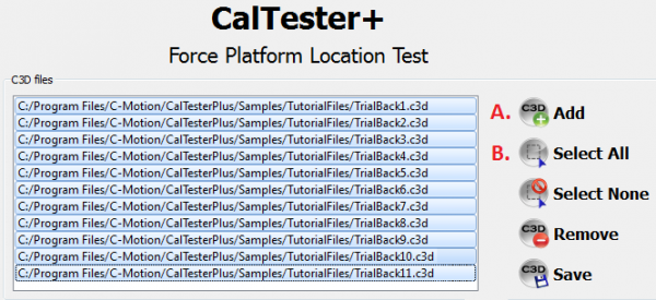
1. Use the add button at the top right-hand side of the screen to load all of the .c3d files that you want to use to create a report from, and select them by highlighting them. For the sample data we will be using the files "TrialBack1.c3d" through to "TrialBack11.c3d".
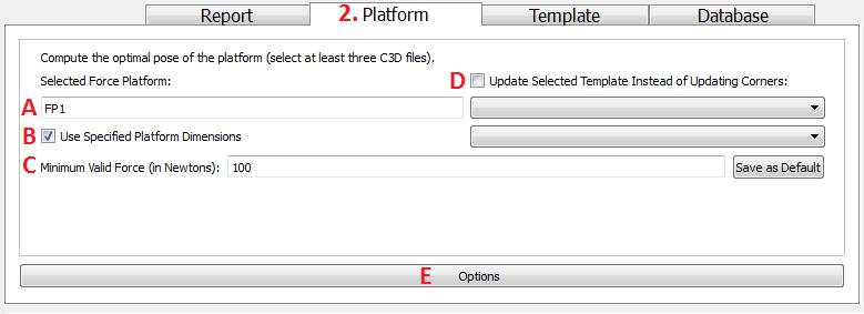
2. Make sure that you are on the Platform tab at the bottom section of the screen.
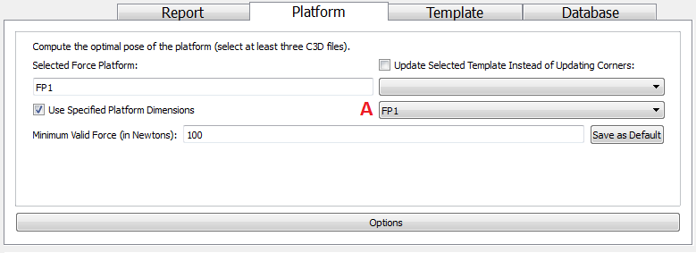
(A) Check that you have selected the force platform number that corresponds to the force platform that the CalTester Rod was used on. If you are using the sample data it is FP 1.
(B) Check the Use Specified Platform Dimensions if you have inputted the force platform sizes into the FP Size tab. If the force plate size has been specified before, select the desired FP, if not, please select the desired plate before completing Step 6 of this tutorial.
(C) Check that the Minimum valid force is set to 100 N.
(D) Do not check "Update Selected Template instead of Updating Corners", this option indicates that the user would like to create a Jig Template which is explained here.
(E) Click on the Options button at the bottom of the screen.
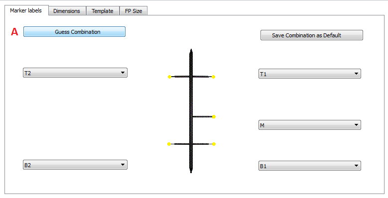
3. Check the CalTester rod labels:
(A) If the CalTester rod is not already labeled click the Guess Combinations button.
(B) Verify that the CalTester Rod has been appropriately labeled. The proper labeling for the sample data is shown below. The Save Combination as Default button can be used if this is a naming convention that you will be reusing.
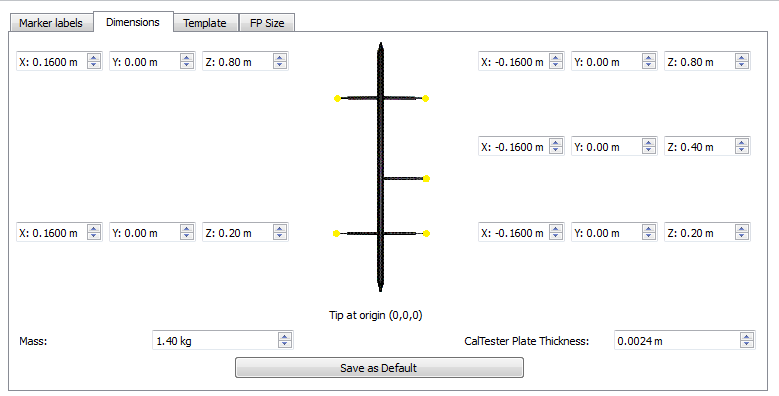
5. Check that the dimensions of the CalTester Rod are correct.
- If you are using the sample data or the CalTester Rod manufactured by Motion Lab Systems use the values that are specified below.
- If you have made your own rod you will need to enter the correct measurements. See here for more information.
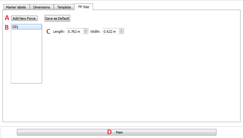
6. Enter the size of your force platforms into the FP size tab.
(A) If not FP exists, click "Add New Force" to populate the list box
(B) Select the desired FP (FP1 for this tutorial)
(C) Enter the correct dimensions of your force platforms from the manufacturer's documentation provided with the force platform. The "Save as Default" button will make these measurements the defaults.
(D) Click "Main"
- If you do not enter the size of your force platform, the C3D corners are used to estimate the size.
6. Ensure the desired C3D trials are still selected, and the settings on the main tab are correct.
(A) If the FP size was specified , ensure the desired FP is selected in the drop down (FP1 in this tutorial).
7. Click on the Go button at the bottom of the screen.
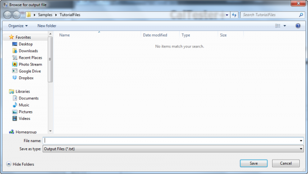
8. The program will ask you where you want to save the text file that has been created with the outputs.
9. The text file should contain a readout similar to what was produced below from the sample files.
- Output for force platform 1:
- ======== Corrected Locations (in mm): ========
- Corner 1: 644.1738, 628.6154, -28.8165
- Corner 2: 648.4933, 6.6324, -27.2725
- Corner 3: -113.4869, 1.3444, -25.7802
- Corner 4: -117.8064, 623.3274, -27.3242
- Force platform Center:
- 265.3435, 314.9799, -27.2984
- ===============================================
- Rotation Matrix (into lab space):
- -0.006945 0.999974 -0.001941
- 0.999973 0.006940 -0.002496
- -0.002482 -0.001958 -0.999995
- Cardan angles to rotate from lab to force platform
- Angle 1 (x): 179.857
- Angle 2 (y): -0.111219
- Angle 3 (z): -89.6019
- Cardan angles to rotate from force platform to lab space
- Angle 1 (x): 179.888
- Angle 2 (y): -0.142226
- Angle 3 (z): -89.6019
- Nexus orientation parameters:
- -0.199561
- -0.024245
- -89.6022
10. This data can now be inputted into the data collection software you are using in order to optimize the force platform location.
