Force Platforms
| Language: | English • français • italiano • português • español |
|---|
Note: This page addresses the representation of external forces and how these forces are included in the inverse dynamics calculations. If you are searching for the computation of Forces and Moments, see the section on Inverse Dynamics.
Force Platforms are commonly used for biomechanical analyses. So common that there is a fairly laissez-faire attitude towards force platform data. Many users don't realize the complexity of computing the ground reaction force vector in the laboratory coordinate system (where it is actually needed for Inverse Dynamics calculations), and, therefore don't take the time that is required to ensure that the data are correct. Issues related to force platform coordinates are described below, but we feel it is necessary to emphasize one topic above all others. The location of the ground reaction force relative to the ankle is the biggest source of error in Inverse Dynamics analysis of gait. Surprisingly few laboratories, however, undertake the challenge of verifying the location of the force platforms within the 3D motion capture volume (see our CalTester section), or verifying the scaling and offset parameters on the ANALOG signals. This reluctance to perform a straightforward test inevitably leads to pain later on during your analysis and, in the worst cases, can make your data unusable.
Verify Force Platform Parameters
A common challenge for a manufacturer creating C3D formatted data files is the declaration of the Force Platform properties in the parameter section of the file. These parameters specify how the ANALOG signals stored in the C3D file should be transformed into the GRF, COFP, and FREEMOMENT signals by Visual3D. Before continuing with your analysis, ensure that your Force Platform parameters are correct. These parameters can be modified using the Modify_Force_Platform_Parameters command.
Calculating Force Signals
Visual3D transforms force signals from the Force Platform's coordinate system into a Ground Reaction Force in the Lab's coordinate system using the locations of the Force Platform's corners, which are numbered from 1 to 4. The locations are specified in the Laboratory Coordinate System in units consistent with the POINT data. The order is specified by the quadrant numbers in the force platform coordinate system using the specific order (+x,+y), (-x, +y), (-x, -y), ( +x, -y). These corner locations allow Visual3D to calculate a transformation matrix which is then used to transform the force vector from the force platform coordinate system (in which it was collected) into the laboratory coordinate system where it is used for the analysis.
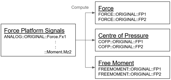
The Ground Reaction Force is represented by 3 vectors: Force, Center of Pressure, and Free Moment. These Ground Reaction Force vectors are computed from the ANALOG signals recorded from the force platform, with the calculations performed as specified by the force platform manufacturer, and the location of the force platform in the laboratory. Within the Visual3D data tree the resulting Force signal is stored in the FORCE folder; the Center of Pressure signal is stored in the COFP folder; and the Free Moment signal is stored in the FREEMOMENT folder.
Filtering Force Signals
On occasion it may be desirable to filter your force signals. There are two possible ways to achieve this, we recommend the former.
1. Filter the ANALOG signals and select the option to use PROCESSED ANALOGS. In this case you will not need to filter the resulting FORCE, COFP, and FREEMOMENT signals.
In order to use PROCESSED ANALOGS, verify in the settings menu that the option Use Processed Anglogs for Ground Reaction Force Calculations is checked. If this is the case, then Visual3D will calculate the FORCE, COFP, and FREEMOMENT signals using the signals found in ANALOG::PROCESSED. If the PROCESSED folder does not exist, then Visual3D will default to using the ORIGINAL folder instead.
2. Filter the FORCE signals directly. In this case you should also filter the COFP and FREEMOMENT signals.
In order to use these PROCESSED signals, verify in the settings menu that the option Use Processed Targets for Model/Segment/LinkModelBased items is checked. If this is the case, then Visual3D will calculate any kinetic and kinematic signals using the signals in the PROCESSED folder of the TARGETS, FORCE, COFP, and FREEMOMENT signal types. Again, if the PROCESSED folder does not exist, then Visual3D will default to using the respective ORIGINAL folders instead.
Minimum Force
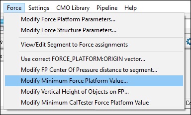
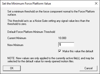
Visual3D's Force menu contains an option to set a threshold for force platform/structure data.
Applying a threshold value to the force signals ensures that If the computed force is less than the minimum force, then the FORCE and FREEMOMENT are set to zero, the COFP is set to DATA_NOT_FOUND. This value can also be set using the pipeline command Set_Force_Platform_Threshold. This command is listed under the Force category of the pipeline commands. This threshold value is used to remove noise from the force signals. Often for instrumented treadmills this value must be set higher than for overground gait trials.
Force Assignment
In order to include a force in the Inverse Dynamics calculations it is necessary for the force to be assigned to a segment. Visual3D will attempt to assign the forces automatically, but these automatic force assignments can be verified and modified using the Force > View/Edit Segment to Force Assignments dialog.
Automatic force assignments are created based on the distance between the segment's center of mass and the force plate center of pressure. The distance between the segment and the center of pressure can be modified by going to Force > Modify FP Center of Pressure distance to Segment. The default value of 0.2m has proven to be an acceptable value, so users should refrain from modifying this value unless they have a very good reason.
Using the View/Edit Segment to Force Assignments dialog, the user has the option of specifying a Custom Force. These custom forces must always be assigned manually.
Force Structures
In recent years force sensors have been included in a variety of structures, such as instrumented stairs and treadmills. Visual3D models these instruments as Force Structures. which are really force platforms attached to structures or to contiguous force platforms spaced in a grid.
C3D Parameters
If your data collection includes Force Platform data, then the C3D file's Parameters section contains information necessary for Visual3D to calculate the FORCE, COFP, and FREEMOMENT signals from the input ANALOG signals. These parameters include:
- FP_TYPE - The type of Force Platform.
- FP_USED - The number of Force Platforms used. If none are used, then this parameter is 0.
- FP_ZERO - The range of frames used to calculate an average baseline value for each ANALOG signal that is then subtracted from every frame.
- FP_ZEROS - Accommodate trials in which it isn't feasible to use the same ZERO frames for all platforms.
- FP_ORIGIN - The origin of the Force Platform's coordinate system. This definition varies according to the Force Platform type.
- FP_CHANNELS - The channel numbers of the ANALOG signals recorded from the Force Platform. These channel numbers vary according to the Force Platform type.
- FP_CORNERS - The locations of the Force Platform's corners in the Lab's coordinate system, specified in units consistent with the POINT data. The order of the corner locations is specified by the quadrant numbers in the force platform coordinate system: (+x,+y), (-x, +y), (-x, -y), ( +x, -y).
Learn More
Complete the Visual3D Force Platforms tutorial to gain hands on experience with the concepts and dialogs covered on this page.


