Pointer-C3D Overview
| Language: | English • français • italiano • português • español |
|---|
Pointer-C3D is a standalone application for creating virtual markers using C-Motion's pointer (which is no longer made or sold).
The pointer is used to identify locations in space without having to place reflective motion capture markers at the location. These locations can be resolved into any local coordinate system (e.g. relative to 3 non-colinear points) and can therefore be used to represent virtual markers that are tracked by this local coordinate system.
The pointer is often used to identify virtually an anatomical location used for defining a biomechanical model of a segment. The process for creating a biomechanical model is part of Visual3D's functionality.
The interface supports passive and active marker setups with custom pointers and vendor provided pointers, but it also has special automation and event recognition capabilities. Dr. Roy Davis has developed a spring-loaded system for identifying a location and event in 3D space. This technology was licensed from Shriners Hospitals by C-Motion, who now manufactures the device.
The functionality is based on our implementation of a digitizing pointer in Visual3D
One major difference is that the stand alone program does not create Visual3D Landmarks. The virtual markers identified by the program are stored as Targets in a c3d file. Other software that opens the c3d file will see this points as markers; the POINT DESCRIPTION in the c3d parameters identifies these markers as digitized markers.
Tutorial
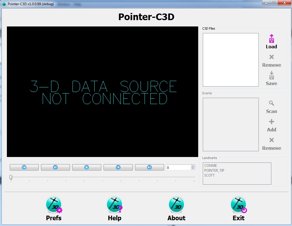
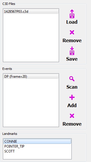
- This is the main window for the Pointer Application
- it contains:
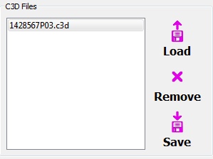
- a list box containing the active c3d files loaded into the workspace
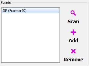
- a list box containing Event labels within the selected c3d file.
- a 3D viewing window for displaying the contents of a c3d file.
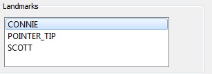
- a list box containing the landmarks (virtual markers) that are to be identified
Landmark Definition
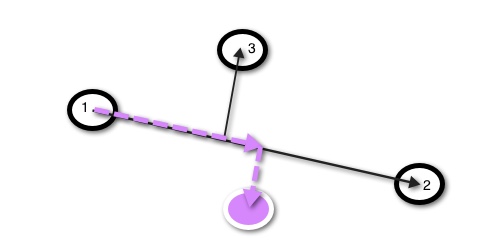
- Given 3 locations (black circles) a local coordinate system is constructed
- In the 2D image shown, the coordinate system is defined as a vector from point 1 to point 2, and a vector perpendicular to this line
- The 3 black circles are attached to a rigid body
- Given the location of the tip of the pointer at an instant in time in motion capture coordinates (purple circle), the location of the tip is transformed into the local coordinate system of the 3 markers (in this figure, represented by the purple dashed vectors).
In 3 dimensions (XYZ), the local coordinate system is created as follows.
- Origin = Location of Point 1 (P1)
- Z-axis = unit vector from P1 to P2
- W-Axis = cross-product of (Z-axis and unit vector from P1 to P3)
- Y-Axis = cross-product of (Z-axis and W-axis)
- X-Axis = cross-product of (Y-axis and Z-axis)
Preferences
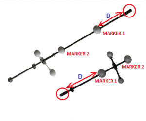
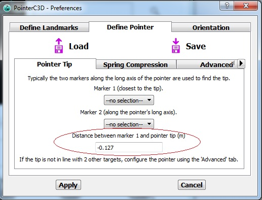
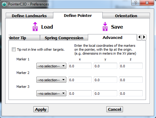
User must measure the distance from Marker 1 to the tip of their pointer and input this specific number
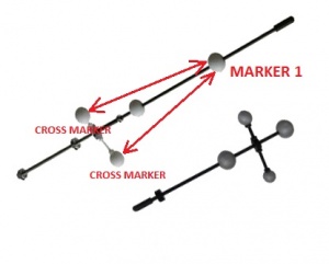
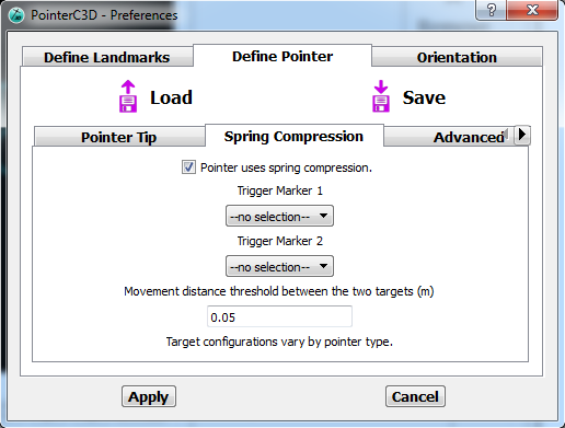
Note: Only the larger pointer uses a spring
This tab is used for specifically defining the location of the pointer markers
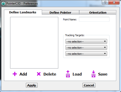
This tab is used for defining landmarks
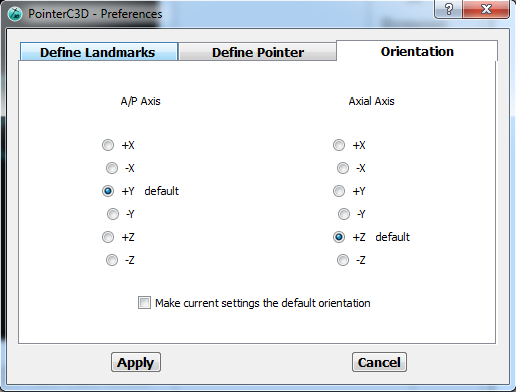
This tab is used for changing the orientation of the pointer if necessary
Load c3d Files
Add an Event
List of Digitizing Landmarks
Create a Landmark
- Select a c3d file
- Select an Event
- Select a Landmark
The landmark will be created automatically and should appear in the 3D Viewer
All c3d files in the list box will have the landmarks created.
If you save the c3d file, the landmarks will be exported as markers to the c3d file.
