Treadmills
| Language: | English • français • italiano • português • español |
|---|
There is a lot of information on the wiki about implementing treadmills in Visual3D, this page is designed to organize that information in one place.
For the most part, processing treadmill data in Visual3D is the same as processing overground data, but there are times when extra information must be taken into consideration.
Kinematics

If you are using a standard treadmill or an instrumented treadmill, you will need to account for the treadmill speed and direction when calculating certain measures, such as the temporal distance measures.
Temporal Distance Measures
Visual3D's built in Temporal Distance command is designed to handle treadmill data.
When calculating temporal distance measures while the subject is walking on a treadmill, it is important to specify the orientation of the treadmill in lab space (Direction), and the speed of the belts (Speed).
For user's using a split belt treadmill with the belts running at different speeds, "Use Split Belt Speeds" must be selected and the different speed of each belt must be specified. If both belts are running at the same speed, do not check "Use Split Belt Speeds" and only specify one speed.
Kinetics
Zeros
Typically, the force platforms are "zeroed" during a specified frame range of each trial. For example, during typical over ground gait, the force platforms are unloaded at the start of the trial, so the average force signal during frames 1-100 would be averaged and subtracted from the trial. For force platform trials, typically the trial starts with the subject on the force platform, so it cannot be assumed that the platform is unloaded during the first 100 frames of the trial.
The frame range is specified in your force platform parameters (which is specified in your motion capture software).
More information about FP Zeros and how to implement them, can be found here.
Locating Force Platform Corners
When calculating kinetics, it is important that the force platform be accurately located in the motion capture volume. With typical overground force platforms, the user is able to see the force platform corners, making it easier to define the location of the force platforms. With instrumented treadmills, the belts cover the surface of the platform, making it difficult to define the exact location/orientation of the force platforms.
The Platform Mode in CalTester can be very useful to identify the position/orientation of the force platforms. The force platforms should only be located in your lab volume once *.
If the force platforms are going to move (for example, an incline/decline treadmill), it will be necessary to update the force platform corners each time the treadmill position has changed. Two methods to update the force platform corners are described below in the "Inclined Treadmill" section.
Inclined Treadmill
Background

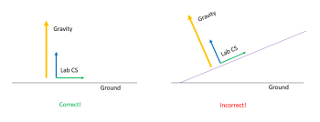
To calculate dynamics, Visual3D must account for gravity. Visual3D defines gravity along one of the principal axes of the lab, which means the origin of the motion capture volume should be set level with the ground. If the origin is set by placing an L-frame on the treadmill, the treadmill cannot be inclined when the origin is set (it must be level).
Most labs define the position and orientation of the force platforms in the treadmill's level position in the motion capture volume. This makes sense because the treadmill is most often in used in the level position, and many labs set the origin of the lab on the treadmill (and the treadmill must be level if you are going to do this). This means the position and orientation of the force platform corners is incorrect when the treadmill is inclined.
Two ways to handle this are:
- Use targets to define the force platform corners when the treadmill is inclined
- Use a jig to define the location of the force platform when the treadmill is inclined
These methods are described below.
Since targets cannot be placed directly on top of the force platforms (due to the treadmill belts), using a jig should result in more accurate force platform location.
Motion Capture Calibration (Placing the Wand)
In Visual3D, gravity is defined along a principal axis of the lab. When you set the origin in your motion capture software, the vertical axis is perpendicular to the plane the calibration tool (wand or L-frame) is on. This means if you defined the origin of the lab by placing the calibration tool on an inclined surface (like an inclined treadmill), gravity will be pointing in the wrong direction!
Using Targets to Define the Corners
Targets may be placed on the treadmill to define the force platform corners and the force platform parameters may be updated based on the location of the targets in 3D space.
An example of this is described here.
Using CalTester Plus
A jig (or cluster of 3 targets) can be used to define the location of the force platform. To create a jig, you need a set of three targets that will have the same position/orientation relative to each other, and relative to the force platform. For example, consistently placing three targets in the same location of the treadmill would act as a jig.
When using a jig (a cluster of targets), the user must first define the location of the force platforms in relation to the targets. This step should be done once *. Instructions to complete this step can be found in the CalTester Locate the Jig Tutorial.
Once the location of the force platforms has been found, you can now use the targets to define the force platform corners in 3D space. This would be done during each collection.
To do this you would calibrate the lab and set the lab origin with the treadmill level. Then place the jig on the treadmill. You could then do one of the following: (1) You can then incline the treadmill and collect a trial with just the jig, and update the force platform parameters in your motion collection software, (2) You could also collect an inclined trial with the subject walking on the treadmill where the jig (or a trial with just the jig) and update the force platform parameters in Visual3D when post processing. Instructions to complete this step can be found in the CalTester Use Jig to define FP corners Tutorial.
* NOTE: It is a good practice to use CalTester every few months to locate your force platforms. By using CalTester periodically, you are able to check that nothing in your lab has changed (the wand is not bent, the lab is not being set differently, etc.)
