Modeling Overview
| Language: | English • français • italiano • português • español |
|---|
At the core of Visual3D is the development of a flexible biomechanical modeling tool that can be used to define an unrestricted number of rigid segments and link them together in a systematic fashion. These segments may be linked implicitly through the motion capture data (e.g. segments in the experiment probably didn't disarticulate) or explicitly through the specification of constraints. The first scenario is handled in Visual3D by assuming that each segment is mathematically independent of all other segments (6 Degrees of Freedom). The second scenario is handled by allowing the specification of joint constraints (Inverse Kinematics).
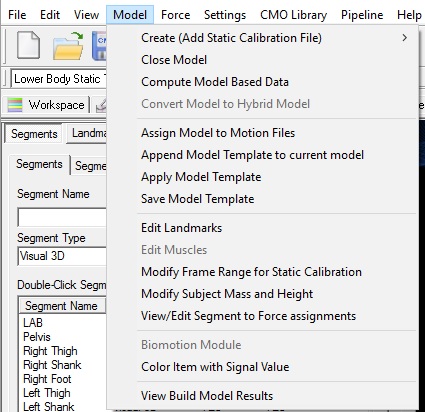
Assign Model to Motion File
Allows the user to specify which model is to be applied to a movement trial.
Visual3D allows many movement trials to be applied to one model, but only one model file may be applied to a movement trial.
A movement trial that has not been assigned to a model will not have segments.
A Segment
A segment is a rigid object defined geometrically by a local coordinate system and a length. Each segment is treated as ideally rigid, i.e., it does not deform in response to applied forces, and is allowed to exist anywhere in space.
Visual3D assumes that the local coordinate system is capable of moving in space, so it is assumed that a sensor is attached to the segment to track this movement. The motion capture system (regardless of the type) tracks the position and/or orientation of the sensor and Visual3D computes the pose (position and orientation) of the segment from the transformation between sensor coordinates, segment coordinates, and joint constraints. The term sensor is used very loosely here because Visual3D actually assumes that markers are attached rigidly to a segment, or that a segment is connected to other segments by a "joint". Visual3D will not allow a segment to be defined that doesn't not include a tracking sensor.
Segment Properties
A segment may have, but does not necessarily have to have, inertial properties.
- The default mass is based on [Dempster's regression equations].
- The default moment of inertia and location of center of mass are computed assuming that a segment as a geometrical shape (cylinder, cone, sphere, ellipsoid).
- Optionally, the user may specify explicitly the inertial properties of the segment.
A segment may have, but does not necessarily have to have, a decoration.
- The default decorations are a surface model which is rendered for the animation. These surface models can be specified as either an Alias Wavefront .obj format or VRML .wrl format. This decoration is exclusively ornamental, and has no affect on the kinematics or kinetics of the segment.
Model Subject Metrics
The subject data tab allows for subject measurements, subject information, and scalar data related to segment calibration to be entered.
- Subject Data may be defined as a floating point value, string, or an expression.
To create a new Subject Data item, click the Add New Item button. This will bring up a dialog to enter the new subject data Name and it's value or expression.
- Subject Data may be used in other model dialogs as part of an expression.
