Tutorial: Building a Model
| Language: | English • français • italiano • português • español |
|---|
NOTE: It's recommended to use the updated version of this tutorial found here!!!!
Overview
There are 6 basic steps to performing an analysis of motion capture data in Visual3D:
- Create a model of your subject(s) using a standing trial, and define the linked segments.
- Explore the data from your movement trials, and associate this data with your model.
- Perform any signal and event processing required for your application.
- Define any biomechanical model-based calculations, such as joint angles, moments, powers, and other computed values
- Generate the desired kinematics and kinetics reports.
- If desired, export data to an external file for statistical processing.
In this tutorial we will load a standing calibration trial and define various segments to create a lower-body a gait model. The techniques learned here will be consistent with all Visual3D models. However the model described in this tutorial is only designed to illustrate the principles of model building and should not be considered the Default Visual3D lower-body model. Once the User learns the basics of building models it is up to him or her to decide what model and marker set is most appropriate for their analyses.
During this tutorial, you will learn how to:
- Create a model that exists conceptually within the Workspace.
- Define segments within the model using Anatomical markers and Tracking markers.
- Work with various viewer controls
Key Concepts
A calibration file (often referred to as a Standing Trial or a Static Trial) is a short motion capture of the subject in a stationary pose. Marker positions are averaged automatically over all frames to compensate for noise in the data. NOTE: If the subject moved during the standing trial, a subset of frames, in which the subject is stationary, can be selected for computing the average locations of the markers. The command Modify Frame Range For Static Calibration is located in the Model Menu items.

In this figure, Anatomical markers are placed at anatomically relevant locations (e.g. palpable bony landmarks near segment endpoints). Tracking markers are placed at convenient locations for tracking the segments. Suggested rules for marker placement on rigid clusters is described in the following article:
Cappozzo A, Cappello A, Della Croce U, Pensalfini P (1997) Surface-Marker Cluster Design Criteria for 3-D Bone Movement Reconstruction. IEEE Transactions on Biomedical Engineering, 44 (12), p 1165-1174.
Preparing for the Tutorial
- Ensure that version 3.0 or later of Visual3D has been downloaded and installed.
- Download the standing calibration file from the website: Lower Body Static Trial.c3d
- Save this file in the folder where you plan to save your motion capture files.
NOTE: The file Tutorial1.cmo contains the end results of this tutorial.
It may be useful as a secondary resource for verifying your progress. - Launch the Visual3D program from the Start menu.
The program will open to the main workspace.
3D Viewer Animation Controls
The viewer is a 3D display (using the OpenGL libraries) of your marker set as seen from multiple camera angles.
Left Mouse Button (Pan)
The left mouse button is used to modify the orientation of the 3D model. Holding down the left mouse button and moving the mouse up and down rotates the model up and down, moving the mouse from side to side rotates the model from side to side.
Right Mouse Button (Zoom)
The right mouse button is used to modify the scaling of the model. Holding down the right mouse button and moving the mouse up or right moves the camera closer to the center of the model (increases the size of the image displayed). Holding down the right mouse button and moving the mouse down or left moves the camera further from the center of the model (decreases the size of the image displayed).
Center Mouse Button (Move)
Holding down the center mouse button (or both the left and right mouse buttons together on a 2-button mouse), allows the user to shift (translate) the model from side to side and up or down.
Note: You will notice that once you move the model a white cross-hair is temporarily added to the scene. This is provided to assist you with centering your model in the scene.
Modify the Viewer Settings
What you see in the 3D viewer varies with the viewing options you select.

Frontal View:
Sets the camera's perspective to view the front of the model from the anterior direction as defined by the lab's anterior/posterior axis.
Sagittal View:
Sets the camera's perspective to view the side of the model from the alter direction as defined by the lab's medial/lateral axis.
Perspective View:
Allows you to view the model from any angle. This is the default view when the 3D Viewer is first opened. This view allows you to choose the camera's perspective by dragging the mouse around the scene.
Reset Camera Perspective:
Sets the camera to look at the lab origin. If you have gotten "lost" in the scene, you can use this button to quickly get you back to a "known" point, the lab's origin.
Toggle Marker names:
Cycles through target labels, target labels with landmark labels, or no target labels.
View Segments:
Clicking the View Segments toggle ![]() button will toggle on and off the model files assigned to the segments. The model files are wire frame objects formatted as either a .v3g or .obj file or a VRML .wrl file. The model file is usually a representation of the bone(s) used for the 3D animation. In the example the model file is a 3D representation of the pelvis bone.
button will toggle on and off the model files assigned to the segments. The model files are wire frame objects formatted as either a .v3g or .obj file or a VRML .wrl file. The model file is usually a representation of the bone(s) used for the 3D animation. In the example the model file is a 3D representation of the pelvis bone.

Note: The 3D animation object is purely for visualization. You can rotate, scale or move the bones relative to the segment coordinate system and it will not affect the analysis.
View Segment Geometry:
To view the geometry click the View Segment Geometry toggle button ![]() on the toolbar.
on the toolbar.

- The width of the cylinder is defined by the endpoint radii of the segment.
- The depth of the cylinder is equal to one-half the distance from anterior to posterior.
View Segment Lines:
View segment lines allows you to view a "stick figure" of the segment(s).
click the View Segment Lines ![]() toggle button.
toggle button.
The yellow segment lines displayed are:
A vertical line between the segment endpoints
Two horizontal lines between the medial and lateral radii of the segment (e.g. from the segment endpoint to the medial and lateral borders of the segment, which are one radius away.)
Create a Hybrid Model
- Start -> Programs -> C-Motion -> Visual3D Create a new model using the standing trial
- From the Model menu, select Create - Hybrid Model from C3D file.
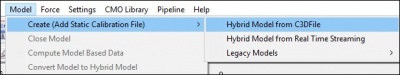
- Select Visual3D Hybrid Model.
- A dialog titled ”Select the calibration file for the new model” will appear;
select ”Lower Body Static Trial.c3d.” Click Open.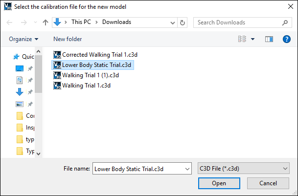
- Visual3D will switch to Model Building mode automatically. The 3D viewer will display the average value of the marker locations from the standing file. The dialog bar to the left of the screen will contain a list of segments, which by default will contain only a segment representing the Laboratory (e.g. Motion Capture Volume).
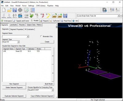
Note: Your screen may look slightly different.


Centering the markers in the viewer
- Rotate the model so that if faces you completely.
- Center the model so that it's center of mass is on the cross-hair.
- Rotate the model so that you are viewing it from the side completely.
- Center the model so that it's center of mass is on the cross-hair.
- Rotate the model so that you view it from the top completely.
- Center the model so that it's center of mass is on the cross-hair. Your model should now be completely centered.
Identifying Markers
- Clicking an individual marker highlights it and displays a label with its name and location. Clicking it again will unhighlight it and remove the label.
- The
 button toggles between marker numbers, marker names, and no annotation.
Creating the Pelvis Segment
There are many possible markers for a pelvis segment that make sense anatomically, and have a history in the biomechanics community. The most common marker set is the Helen Hayes marker set shown here.
In this tutorial we are presenting a pelvis segment that is defined similarly to all segments in Visual3D, so we refer to it as the Visual3D Pelvis
- From the Segment Name box, select Pelvis.
- From the Segment Type box, select Visual3D.
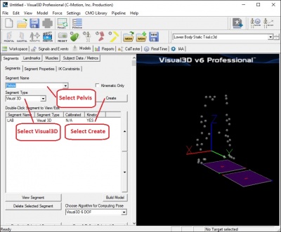
- Click Create.
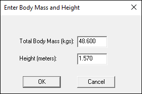
- A dialogue box labeled Enter Body Mass and Height will open because Visual3D needs the subject to be assigned a mass and a height. For this example, Enter 48.6 kg and 1.57 m, and click OK.
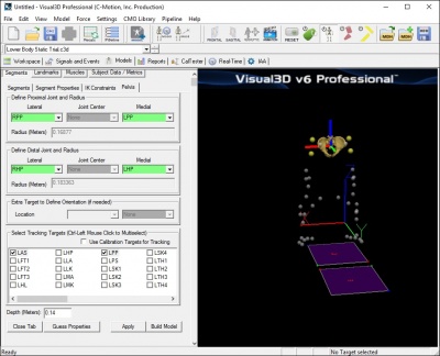
- In the Pelvis tab, enter these values:
- Define Proximal Joint and Radius: (Right and Left Iliac Crest Markers)
- Lateral: RPP
- Medial: LPP
- Define Distal Joint and Radius: (Right and Left Greater Trochanter Markers)
- Lateral: RHP
- Medial: LHP
- Select Tracking Targets: LAS, RAS, LPP, RPP (Select all 4)
- Depth: 0.14000 (Physical depth of the pelvis; Mid ASIS to Mid PSIS)
- Click Build Model to build the segment. You should now see a pelvis segment on your standing model. If you do not see the pelvis segment after clicking Build Model, double check the values you entered in the last step.


View the Pelvis Segment Coordinate System
It is often helpful to isolate the segment's coordinate system in order to validate that it is setup correctly. This view can also help you visualize where the center of gravity for a segment is located. Follow the procedure below to isolate the segment's coordinate system by toggling off the other views. When you are done you will be left with the Coordinate System of the Pelvis as represented by a Red Line (x-axis), Green Line (y-axis) and a Blue Line (z-axis) in the image below.
Note: Each of the view buttons is a toggle button and will either toggle on or off a particular view.
- Click the Views Segment toggle button
 on the toolbar until the pelvis bone disappears (the same effect can be achieved by pressing F5 on your keyboard).
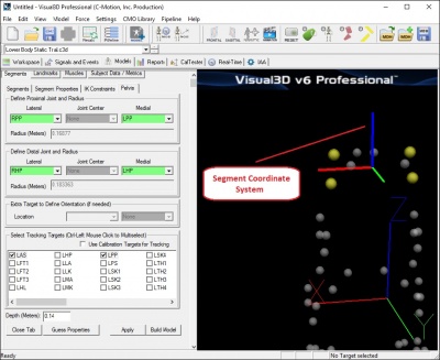
- Click the Views Segment Geometry toggle button
 on the toolbar until you toggle off geometric view the pelvis (the same effect can be achieved by pressing F7 on your keyboard).
Note: If you have followed this tutorial exactly this view may already be off.

Click the Views Segment Lines toggle button ![]() on the toolbar until you toggle off the yellow lines which connect the segment end points.
on the toolbar until you toggle off the yellow lines which connect the segment end points.
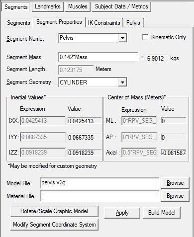
Segment Properties
The following properties are computed based on the calibration of the segment proximal and distal endpoints.
- Segment Length - This is computed based upon the calibration of the segment proximal and distal endpoints.
- Inertial Values - This is computed based upon the segment mass and geometry. These values may be modified only for segments with a CUSTOM SEG (ment) selected for the Segment Geometry.
- Distance from CM (Center of Mass) to Proximal end - This is a multiplier used to modify the distance from the center of mass from the segment's proximal end. This field is only used when CUSTOM SEG (ment) is selected for the Segment Geometry.
View the Pelvis Segment Properties
The Segment Properties dialog modifies general properties which are common to most segments. Some of the most common uses include changing the mass of the segment, the scale and rotation of the object which represents the segment, adding a custom object (such as a golf club or baseball bat), removing the kinetic calculations for a segment, modifying the size and rotation of the segment, and modifying the segment coordinate system.
Segment properties that may be modified
- Segment Name - Changing this will select another segment to modify.
- Kinematics Only - Use this check box for segment where only kinematics need to be calculated (where kinetic calculations are not needed). This is sometimes useful when you want to create a virtual segment where kinetic calculations are not needed such as a virtual foot or virtual lab.
- Segment Mass - The segment mass is defaulted based on the type of segment and the subject mass. To change this value, you may type in a specific value for the mass (in kilograms), or use a formula using existing Subject Data (such as a percentage of the subject Mass). This may be helpful if the subject is using a prosthesis that would have a different mass than the part of the body it replaces.
- Segment Geometry - The segment may be represented internally as a CONE, .CYLINDER, SPHERE, ELLIPSOID or CUSTOM SEG (ment). The geometry of a segment affects the segment's inertial properties and center of mass location. This also affects the segment geometry drawn when view segment geometry is selected in the animation/model builder window. This would be useful if you have a custom segment defined and need to change the default segment geometry.
- Model File - This is the graphic model file (.v3g, .obj, or .wrl) used to draw the segment in the animation/model window. In most cases this would be a bone, but could also be an object such as a golf club, baseball bat, or as you will see in the Just for Fun section below, where a skull is substituted for the pelvis, any object file.
- Material File - Material files can be loaded to change the color of a segment. Material file can only be used with .obj files.
Modify a segment's properties:
- Select the segment name in the Segment Name combo box. The selected segment's properties will be displayed in the dialog.
- To modify the properties, make the desired change in the dialog.
- Click Apply.

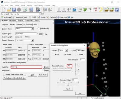
A little fun with the Graphics
You may skip to the next section if you wish. As you will see, it is possible to replace the ”bones” with another bone or object file. As a ridiculous example, you can change the pelvis model to display a skull rather than the pelvis bones.
- Click on the Browse button beside the Model File edit box.
- Open the head.v3g file.
- Click Apply. A 3D image of a head will appear in place of the pelvis.
Note: For older versions of the software this will be head.obj. Visual 3D accepts either file format. - The head will appear upside down because the default segment coordinate system for the head is defined with the top of the head as the distal segment.
- To re-orient the bone:
- click on the Rotate/Scale Graphic Model button
- Set the Horizontal Rotation to 180
- Click OK to accept the new rotation value and close the window.
- Restore the pelvis image before proceeding:
- Change Model File back to pelvis.v3g
- Click Rotate/Scale Graphic Model
- Click Reset.
- Click OK.

Save the data
Save often to prevent loss of files due to power outages or Windows errors.
Save the Workspace to a .cmo file
Maintain a series of .cmo files as you work so that you can revert to a previous step.
- From the File menu, click on Save As.
- In the Save As dialog box label your file MyTutorial1.cmo, navigate to the location of your choice and click Save.
Save the Model Template
Save the segment definitions as a model template (mdh) file to allow you to re-create models using the same marker set.
From the Model menu select Save Model Template.
In the Save As dialog box label your file tutorial_template.mdh, navigate to the location of your choice and click Save.
Apply the Model Template
Now that the model template exists, you can use this template on other data sets.
From the Model menu select Apply Model Template
In the dialog box select the appropriate .mdh file.
Define the Remaining Segments
Create the Right Thigh Segment
- From the Segments tab, select Right Thigh in the Segment Name drop down list box
- Click Create. A new tab labeled Right Thigh will open.
- In the Right Thigh tab, enter these values: Define Proximal Joint and Radius
- Click Build Model. A 3D image of a thigh will appear.
Note: If you receive an error message about inertial properties and custom segments, you may have entered an incorrect number for the proximal radius.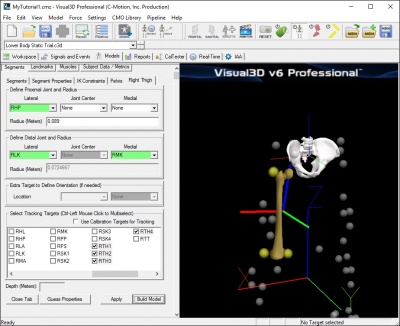
- Click Close Tab before proceeding.
Note: Closing the tab will not affect the model in any way.
Lateral: RHP Joint: None Medial: None Radius: .089 Note: There is no medial marker on the proximal end. Only three markers are needed to create the plane. In this situation Visual3D requires the distance from the marker to the hip joint center (proximal radius). In this tutorial the measured value of the radius was 0.089 meters, but this value should be unique to each subject. This radius value is based on estimating the hip center from palpation while moving the Thigh. Using a caliper the distance from the greater trochanter target to the estimate of the hip center is measured. There is some justification for this prehistoric approach. The Coda pelvis’ hip center is based on the Bell, Brand and Peterson regression equations which came from a limited number of samples and doesn’t account for gender differences (we know exist in the pelvis). Also you could argue that this lateral marker approach is superior to functional joints because it isn’t really subject to soft-tissue artifact. If you have a really talented person placing your markers a lateral proximal target can be useful method for defining the coordinate system of the thigh. This radius value is used in the calculation of the default inertial properties Define Distal Joint and Radius
Lateral: RLK Joint: None Medial: RMK
Select Tracking Targets: RTH1, RTH2, RTH3, RTH4 (Select all 4)
Note: Hold the Ctrl key on your keyboard while you click to make multiple selections.

Create the Right Shank Segment
- In the Segments tab, select Right Shank in the Segment Name box.
- Click on the Create Segment button.
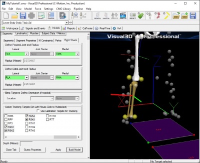
- In the Right Shank tab, enter these values:
Define Proximal Joint and Radius
Lateral: RLK Joint: none Medial: RMK Radius:
Define Distal Joint and Radius
Lateral: RLA Joint: none Medial: RMA Radius:
Select Tracking Targets: RSK1, RSK2, RSK3, RSK4 - Click on Build Model. A 3D image of a shank will appear distal to the thigh.
- Click on Close Tab before proceeding.

Create the Right Foot Segment
- In the Segments tab, select Right Foot in the Segment Name box.
- Click on the Create Segment button.
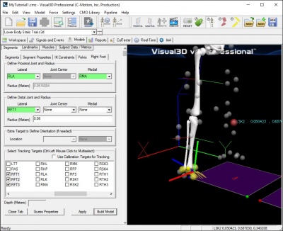
- In the Right Foot tab, enter these values:
Define Proximal Joint and Radius
Lateral: RLA Joint: none Medial: RMA Radius:
Define Distal Joint and Radius
Lateral: RFT1 Joint: none Medial: none Radius: 0.06
Select Tracking Targets: RFT1, RFT2, RFT3 - Click on Build Model. A 3D image of a foot will appear distal to the shank.
- Click on Close Tab before proceeding.
- This is a simple representation of the foot that is adequate for many of the Kinematic and Kinetic calculations in Visual3D. It is not, however, adequate for the calculation of the ankle joint angle; see the joint angle section for further information.

Note: The value of 0.06 was a measurement made on this subject. This value should be measured and should be unique to each subject.
Create the Left Thigh Segment

- In the Segments tab, select Left Thigh in the Segment Name box.
- Click on the Create Segment button.
- In the Left Thigh tab, enter these values:
Define Proximal Joint and Radius
Lateral: LHP Joint: none Medial: none Radius: 0.089
Define Distal Joint and Radius
Lateral: LLK Joint: none Medial: LMK Radius:
Select Tracking Targets: LTH1, LTH2, LTH3, LTH4 - Click on Build Model. A 3D image of the left thigh will appear.
Create the Left Shank Segment
- In the Segments tab, select Left Shank in the Segment Name box.
- Click on the Create Segment button.
- In the Left Shank tab, enter these values:
Define Proximal Joint and Radius
Lateral: LLK Joint: none Medial: LMK Radius:
Define Distal Joint and Radius
Lateral: LLA Joint: none Medial: LMA Radius:
Select Tracking Targets: LSK1, LSK2, LSK3, LSK4 - Click on Build Model. A 3D image of the left shank will appear.
Create the Left Foot Segment
- In the Segments tab, select Left Foot in the Segment Name box.
- Click on the Create Segment button.
- In the Left Foot tab, enter these values:
Define Proximal Joint and Radius
Lateral: LLA Joint: none Medial: LMA Radius:
Define Distal Joint and Radius
Lateral: LFT1 Joint: none Medial: none Radius: 0.06
Select Tracking Targets: LFT1, LFT2, LFT3 - Click on Build Model. A 3D image of the left foot will appear.
Completing the Model
- When all segments have been defined, click on Build Model.
- In the File menu, click on Save to save the file for use in another tutorial.
- Save the model as a Model Template.
Verify the model template
- Clear the Visual3D Workspace - Select File New
- Repeat the initial steps in this tutorial.
- Open the movement trial
- Create a hybrid model using the standing trial
- Assign the movement trial to the model
- Apply the model template. You will find this option under the Model Menu Item.
Proceed to next Tutorial: Visualizing Data